Prevent Servo Damage: Fix A.910 Overload Warning

Prevent Servo Damage: Fix A.910 Overload Warning

When operating high-precision CNC machinery, unpredicted downtime is the ultimate enemy of productivity. Modern industrial machinery relies on complex arrays of sensors and software to monitor operational health. Among the vast array of codes that can appear on a machine controller, the A.910 Overload Warning is one of the most critical preliminary alerts you can receive. Commonly associated with Yaskawa Sigma series drives and adopted by various other top-tier servo systems, this specific warning acts as an essential “canary in the coal mine.” It is the machine’s way of informing you that the servo motor is working significantly harder than its rated capacity, and a complete system shutdown is imminent if the operational stress is not mitigated.

In the high-stakes environment of industrial manufacturing, choosing to ignore an overload warning is a catastrophic and expensive mistake. An overload condition signifies that the servo motor is pulling excessive electrical current for an extended duration, rapidly pushing the internal electromagnetic components and the amplifier’s drive circuits toward their maximum thermal limits. In this extensive, publication-ready guide, we will thoroughly decode the mechanics behind the A.910 warning, systematically explore its mechanical and electrical root causes, and provide an actionable, step-by-step troubleshooting protocol. By following this guide, you will be able to rectify the issue, optimize your machine’s performance, and protect your highly valuable CNC components from permanent thermal damage.
Understanding the Mechanics of the A.910 Overload Warning

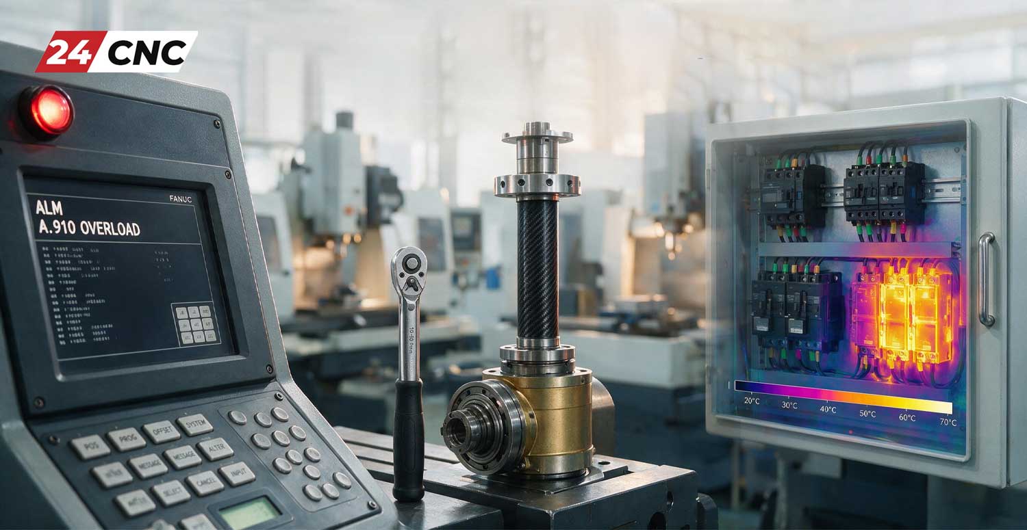
Understanding the Mechanics of the A.910 Overload Warning

To accurately and safely troubleshoot the A.910 warning, maintenance technicians and CNC operators must first grasp the underlying principles of how CNC servo amplifiers and drives calculate and monitor motor health. Every servo system is engineered to operate strictly within two primary torque boundaries: the continuous torque limit and the peak torque limit.

The continuous torque limit represents the maximum amount of rotational force the servo motor can exert indefinitely without exceeding its safe operating temperature. Conversely, the peak torque limit—which can often reach upwards of 300% of the continuous rating—is designed strictly for instantaneous, short-duration demands, such as aggressive acceleration from a standstill or rapid deceleration. If a motor is forced to sustain peak torque for too long, it will overheat and burn out.

The A.910 warning is triggered when the amplifier’s internal microprocessor detects that the effective load torque (often calculated as Root Mean Square or RMS torque) is dangerously close to the motor’s absolute thermal limit over a specific time constant. The drive uses sophisticated internal thermal modeling, constantly analyzing the electrical current being drawn by the motor. When this calculated thermal load reaches a high threshold (typically around 85% to 90% of the trip point for a hard overload alarm), the drive proactively flashes the A.910 warning.

The Crucial Difference Between a Warning and a Hard Alarm

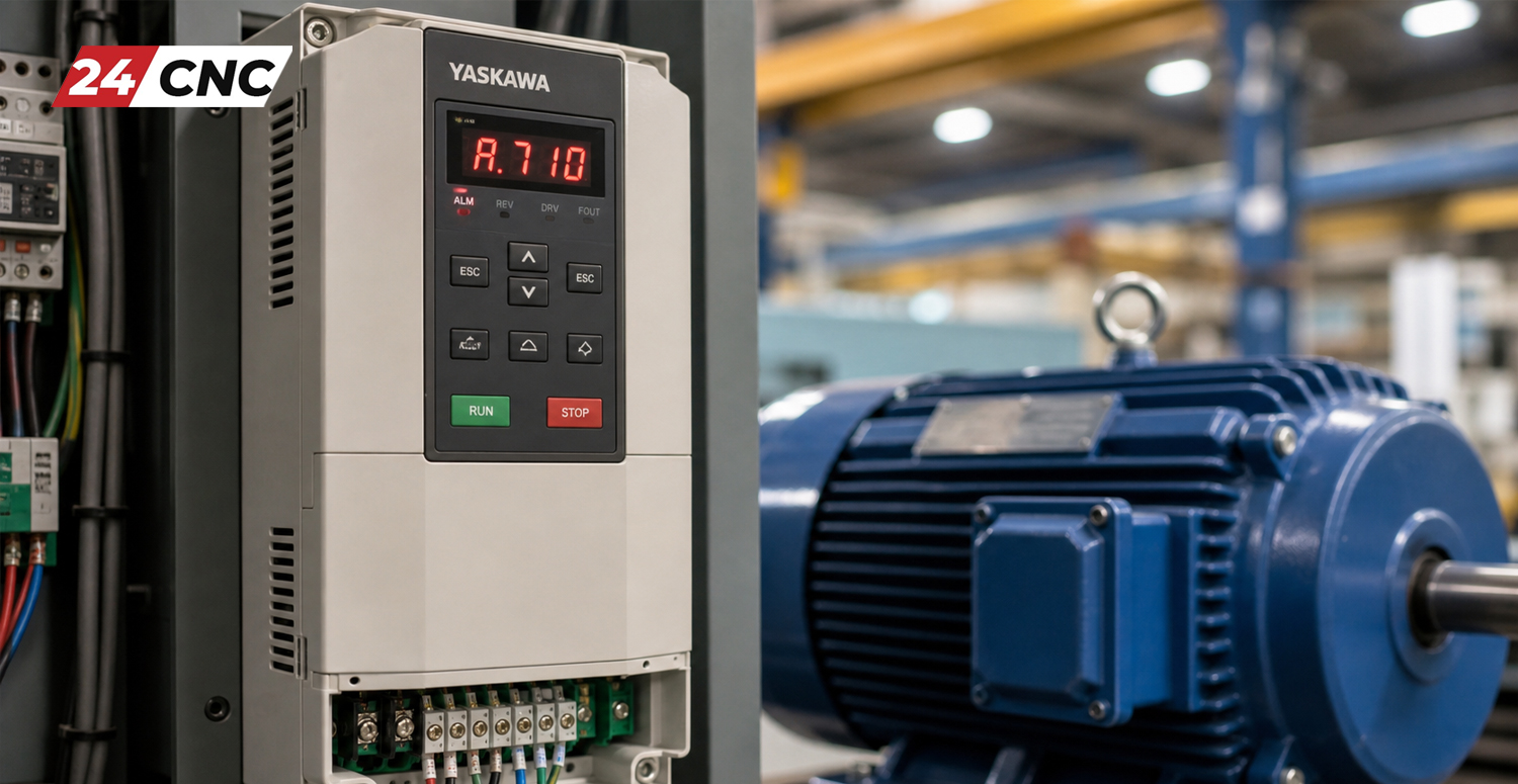
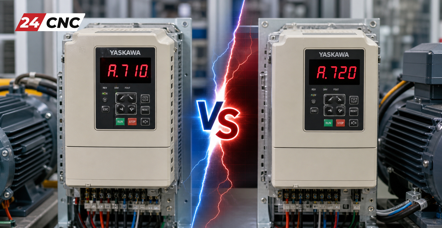
It is of the utmost importance to distinguish between a preliminary warning (like the A.910) and a hard, immediate fault alarm (such as the A.710 overcurrent alarm or the A.720 continuous overload alarm). A warning indicates that the CNC system is approaching a critically dangerous thermal state, but it remains fully operational for the time being. The servo amplifier is effectively warning the operator: “I am reaching unsafe temperature levels; if this current draw continues, I will initiate a protective shutdown.”

A hard alarm, on the other hand, indicates that the thermal or current threshold has been completely breached. In this scenario, the drive actively and instantly cuts high-voltage power to the motor to prevent catastrophic electrical fires, melted windings, or the destruction of internal IGBT modules. By responding to the A.910 warning promptly, you prevent the machine from reaching this hard alarm state.

Primary Causes of the A.910 Overload Warning

Effectively diagnosing the A.910 warning requires a highly methodical and logical approach, as the underlying root cause can originate from mechanical binding, electrical degradation, or even software parameter errors. Below, we detail the most prevalent culprits.

1. Mechanical Binding and Increased System Friction

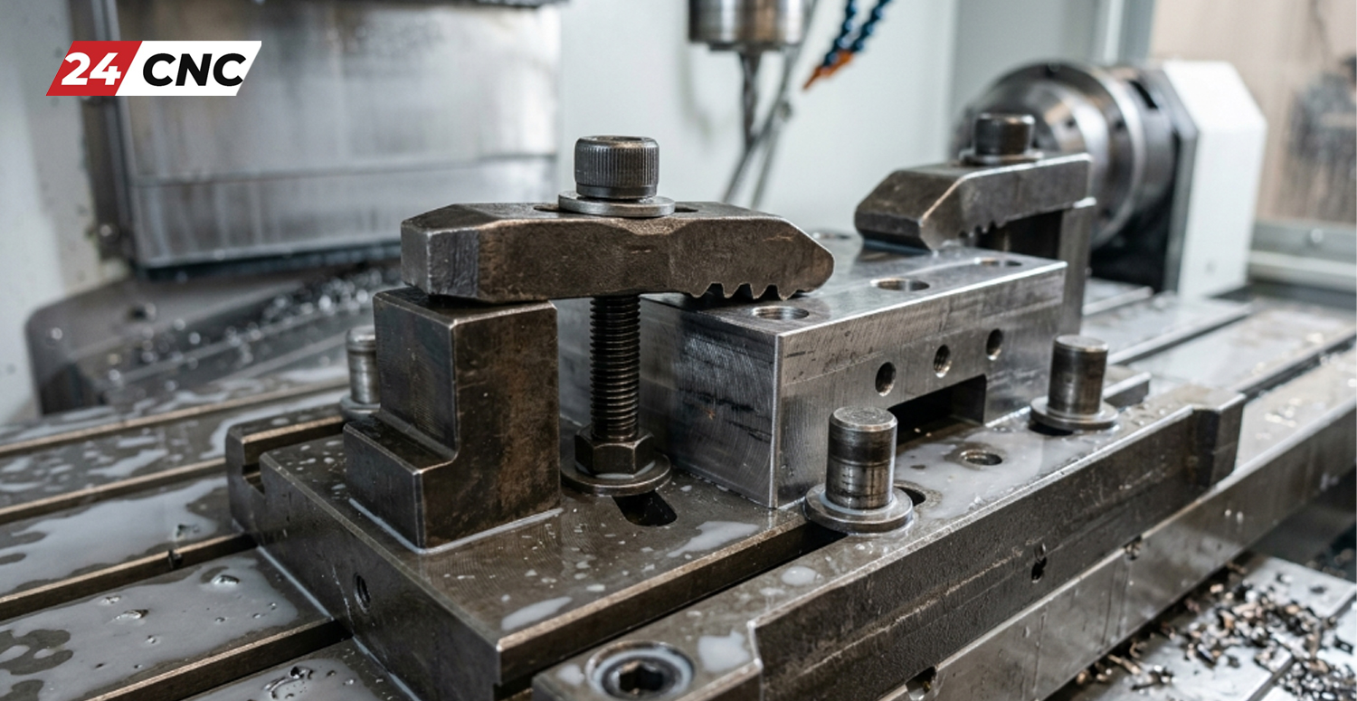
In the vast majority of cases, the most frequent cause of any servo overload warning is an underlying mechanical issue on the machine tool itself. Over years of operation, the moving elements of a CNC machine—such as ball screws, linear guideways, and rotary tables—wear down. Lubrication lines can become clogged with coagulated oil and metal chips, causing way surfaces to run dry. If a ball screw binds, or a gib is adjusted far too tightly, the physical mechanical resistance of the axis increases exponentially.

Because the CNC servo system operates in a closed-loop environment, the controller will continuously command the amplifier to supply more current to the motor to overcome this physical resistance and reach the programmed position. This relentless, high-current electrical draw drastically raises the thermal load on both the motor and the drive, inevitably triggering the A.910 warning as the system fights against its own mechanical friction.

2. Improper Servo Parameter Tuning and Oscillation

Servo motors rely heavily on complex mathematical algorithms and tuning parameters (specifically Proportional, Integral, and Derivative, or PID gains) to execute movements smoothly and with microscopic accuracy. If these parameters are improperly optimized for the actual physical mass and inertia of the machine’s load, the motor may begin to vibrate, oscillate, or “fight” itself.

For example, if the programmed acceleration and deceleration time constants are too aggressive for an axis carrying a heavy workpiece, the motor will consistently draw peak current in an attempt to meet the impossible demand. Furthermore, excessive high-frequency electrical noise caused by poor tuning can induce micro-oscillations that rapidly heat up the copper motor windings, simulating a physical overload condition even when the machine is stationary.

3. Aggressive Machining Applications and Duty Cycles

Occasionally, the machine tool is mechanically flawless and electrically sound, but the programmed CNC operation is simply too demanding for the hardware. If the machine is executing a G-code program that requires continuous, rapid short-stroke movements (such as complex high-speed 3D mold surfacing) without sufficient dwell times incorporated for the motor to cool down, the overall RMS torque demand will easily exceed the continuous rating of the motor. Pushing a machine beyond its original engineered design limits is a guaranteed method for triggering the A.910 warning.

4. Electrical Degradation: Cables and Encoders

Faulty electrical hardware can easily simulate a mechanical overload condition. If the high-voltage power cables connecting the servo amplifier to the motor suffer from degraded insulation, partial internal shorts, or corroded connections, it creates significant electrical resistance. The amplifier must pump increasingly more current simply to overcome this cable resistance, leading to false thermal overload readings.

Additionally, a compromised feedback system is a major culprit. If a rotary encoder begins to fail due to fluid contamination or vibration, it may send erratic or delayed position data back to the drive. You can learn more about this by reading how to troubleshoot inaccurate encoder readings. When the drive receives bad data, it rapidly spikes the current to correct the perceived error, causing massive thermal buildup and triggering the A.910 warning.
Step-by-Step Troubleshooting Guide for the A.910 Warning

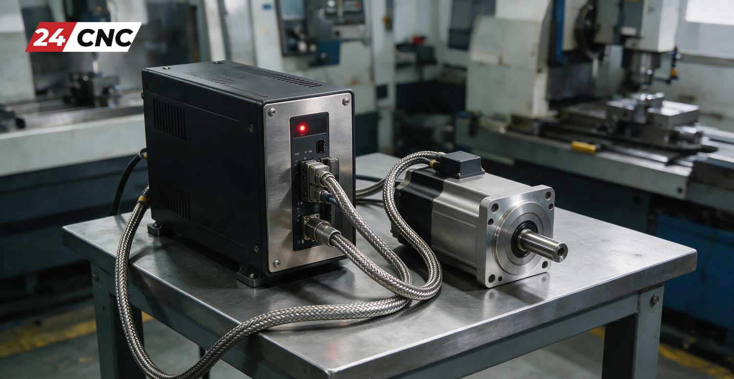
Step-by-Step Troubleshooting Guide for the A.910 Warning

When the A.910 warning inevitably flashes on your controller screen or drive display, it is imperative to stop the machining cycle safely and follow these precise, comprehensive steps to isolate and completely resolve the issue.

Step 1: Conduct a Physical Temperature Check and Isolate the Axis

Before connecting a laptop or tearing apart the machine, use your physical senses. Carefully approach the affected servo motor and feel the external temperature of its casing (use extreme caution, as an overloaded motor can reach temperatures capable of causing severe burns). If the motor is burning hot to the touch, you have a confirmed, real physical overload condition, not merely a sensor glitch. Power down the machine and allow the motor to cool to room temperature before proceeding to prevent internal damage.

Step 2: Perform a Complete Mechanical Decoupling Test

To definitively determine whether the root cause is mechanical or electrical, you must isolate the servo motor from the machine’s drivetrain. Safely lock out the machine’s power and mechanically uncouple the servo motor from the ball screw, belt drive, or gearbox. Once the motor is physically disconnected, attempt to turn the machine’s ball screw or axis by hand using a wrench or handwheel.

The axis should move relatively smoothly with consistent resistance. If you encounter extreme stiffness, grinding noises, binding, or tight spots, the problem is 100% mechanical. You must immediately inspect the thrust bearings, check the automatic lubrication system for blockages, and ensure there is no structural damage to the linear guideways from a previous crash.

Step 3: Test the Servo Motor in a No-Load Condition

With the motor still mechanically uncoupled from the machine tool, power up the CNC control. Carefully use the manual jog function to spin the motor (ensure the motor is safely secured to a bracket so it does not violently twist upon acceleration). If the A.910 warning still triggers while the motor is spinning freely with absolutely zero physical load, the issue is firmly electrical.

This result points directly to a compromised motor (such as shorted internal stator windings), a failing servo amplifier, or severely degraded power cables. For more extensive electrical diagnostics on the drive itself, consult our guide on how to troubleshoot CNC servo amplifier alarms.

Step 4: Monitor Torque Output Using Servo Setup Software

If your machine utilizes modern digital servo drives, connect a laptop directly to the amplifier and launch the manufacturer’s diagnostic software (such as Yaskawa’s SigmaWin+ or Fanuc’s Servo Guide). Utilize the real-time trace function to monitor the internal torque reference and current draw. Run a standard, dry-run machining cycle and observe the torque graph.

If you witness the continuous torque line hovering consistently around the 80% to 100% mark during standard cutting feeds, you are simply overworking the system’s design capacity. In this scenario, you must adjust your CAM programming to reduce feed rates, utilize lighter depths of cut, or increase the acceleration/deceleration time constants to relieve the stress on the motor.

Step 5: Inspect the Regenerative Resistor Circuit

During rapid deceleration phases, a CNC servo motor acts as an electrical generator, sending kinetic energy back into the amplifier as high-voltage DC power. This excess energy must be safely burned off as heat by a component called a regenerative resistor. If this resistor is blown open, shorted, or improperly sized for the application, the drive cannot dissipate the energy efficiently.

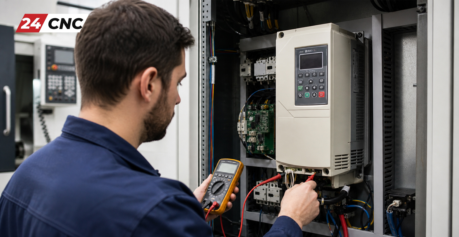
This inability to shed regenerative energy contributes to massive internal heating within the amplifier, which can indirectly trigger overload warnings. Inspect the regenerative resistor circuit using a high-quality multimeter to ensure its resistance matches the manufacturer’s specified ohm rating.

Technical Comparison: Servo Overload Warnings vs. Hard Alarms

For maintenance personnel, understanding the precise staging of servo alerts is vital for prioritizing responses and ordering the correct replacement parts. The table below outlines the critical differences between early overload warnings and catastrophic hard alarms.
System Feature Overload Warning (e.g., A.910) Hard Overload Alarm (e.g., A.710, A.720)
Machine Operational Status Machine continues running but flashes visual alerts to the operator to intervene. Immediate “Servo Off” state; machine stops abruptly, likely ruining the workpiece.
Internal Thermal Threshold Typically triggered at 80% to 90% of the drive’s internal thermal model limit. Triggered precisely at 100% of the internal thermal model limit.
Operator Action Required Finish the current cutting pass carefully, stop the cycle, and investigate mechanics. Immediate hard power down. Requires alarm clearing, resetting, and deep diagnostics.
Risk of Hardware Damage Very Low, provided the operator or maintenance team intervenes promptly. Extremely High. Repeated alarms degrade winding insulation and damage IGBTs.

Proactive Preventive Maintenance to Avoid Servo Overloads

Proactive Preventive Maintenance to Avoid Servo Overloads

In the machining industry, the most cost-effective way to handle an A.910 warning is to guarantee it never happens in the first place. A rigorous, non-negotiable preventive maintenance strategy is the absolute lifeblood of any profitable CNC machine shop. By implementing and adhering to a strict CNC machine maintenance checklist, you will drastically reduce the occurrence of servo overloads and extend the life of your equipment.

First and foremost, maintain the mechanical integrity of the machine. The automatic way lube lines are notorious for becoming clogged with microscopic swarf, dust, and fines over time. When linear guideways and ball screws run dry, the coefficient of friction skyrockets, placing massive, unnatural strain on the servo motors. You must verify weekly that your automatic lubricator is actually dispensing clean oil to all critical pivot points and sliding surfaces.

Secondly, heavily monitor the electrical environment. Servo amplifiers generate immense heat during standard operation, and their internal cooling fans must be fully functional. If the electrical cabinet’s intake filters are clogged with workshop dust or sticky coolant mist, the ambient temperature inside the cabinet will rapidly rise. This elevated ambient temperature severely reduces the amplifier’s ability to shed its own internal heat, artificially lowering the threshold at which the thermal model triggers the A.910 warning. Routinely replace cabinet filters and meticulously clean the cooling fans mounted on both the motors and the drives.

Frequently Asked Questions (FAQ)

Can I simply reset the A.910 warning on my controller and continue machining?

While it is often possible to clear the A.910 warning by power-cycling the machine control or simply allowing the motor to sit and cool down, doing so without addressing the underlying root cause is a highly dangerous practice. Repeatedly ignoring the warning and forcing the machine to run will eventually degrade the servo motor’s internal copper windings or permanently destroy the amplifier’s sensitive internal power components.

Will upgrading to a larger servo motor fix my recurring overload issue?

Upgrading the motor is a very costly and ill-advised “band-aid” fix. While a larger motor inherently has a higher thermal mass and torque capacity, it does not solve the root problem. If the primary issue is mechanical binding, a larger motor will simply overpower the machine’s mechanics, which will likely result in snapping ball screws, shearing couplings, or permanently destroying linear guideways. Always diagnose and repair the mechanical friction first.

How can I verify if my servo motor is suffering from mechanical overload?

The most definitive method is to monitor the continuous torque load percentage in your CNC controller’s diagnostic screens. You can also use the drive’s proprietary setup software via a laptop connection. If the machine is “cutting air” (moving without engaging a workpiece) and the torque load remains steadily above 30% to 40%, you almost certainly have severe mechanical friction in the axis that needs immediate attention.

Is it possible that a malfunctioning encoder is causing the A.910 warning?

Absolutely. If an encoder is intermittently failing or has dirt/coolant contamination on its internal optical disk, it will send erratic position feedback to the amplifier. The drive will desperately attempt to correct these perceived position errors by injecting massive, rapid spikes of current into the motor. This violent current fluctuation rapidly heats the motor and quickly triggers the overload warning.

Conclusion: Stay Proactive with Your CNC Servo Health

The A.910 overload warning should never be viewed as an annoyance; rather, it is your CNC machine’s highly intelligent way of asking for maintenance before a catastrophic and expensive failure occurs. By taking the necessary time to fully understand the intricate relationship between mechanical friction, electrical integrity, and servo parameter tuning, maintenance professionals can quickly and accurately diagnose the root cause of the warning.

Remember that the vast majority of servo overload issues originate not from failed electronics, but from mechanical binding, poor lubrication, or overly aggressive machine operation. By strictly adhering to the step-by-step diagnostic procedures outlined in this guide—starting with physical inspections and moving toward digital torque monitoring—you can confidently resolve the A.910 warning. Doing so will restore your CNC machine to peak efficiency, ensure the accuracy of your manufactured parts, and significantly extend the lifespan of your expensive servo drives and motors.

Need High-Quality Replacement Parts to Fix Your CNC Alarms?

Whether your diagnostics point to a burnt-out servo motor, degraded high-voltage power cables, or you simply need a completely refurbished servo amplifier to get back online, 24CNC provides the premium industrial components required to get your machine running flawlessly again. Don’t let an unresolved alarm halt your production schedule!
Browse Our Premium CNC Parts Catalog Today

Yaskawa A.810 Alarm Fix & Battery Replacement

Yaskawa A.810 Alarm Fix & Battery Replacement

As an industrial automation engineer or a CNC workshop owner, few things are as frustrating as walking up to your control panel on a Monday morning only to find your machine locked up due to an unexpected servo drive error. Among the most common—yet highly misunderstood—errors in the world of motion control is the dreaded Yaskawa A.810 alarm. This specific fault code flashes on the 7-segment display of your Yaskawa Servopack, bringing your production line to a grinding halt.

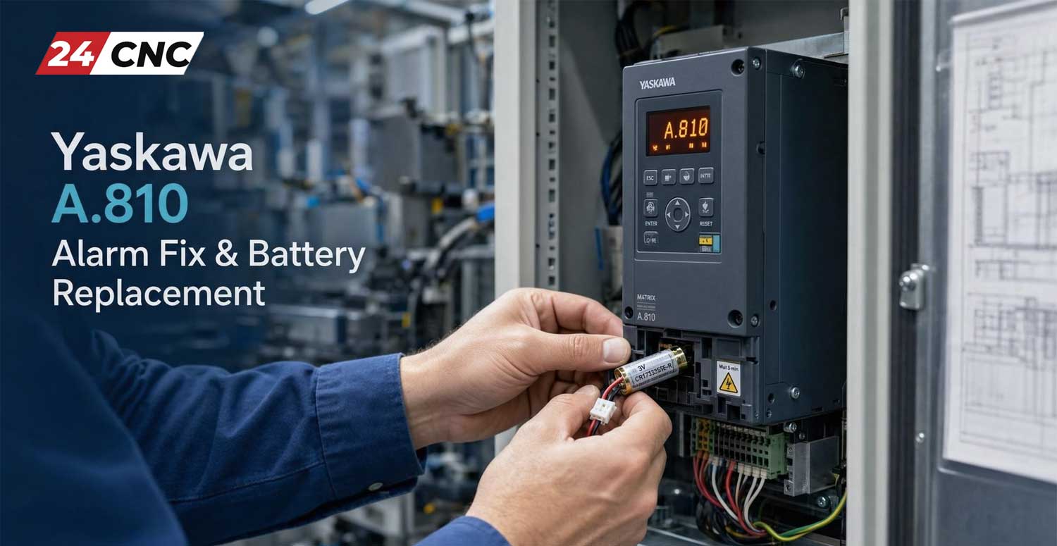
But what exactly does the A.810 alarm mean? In simple terms, it indicates an Encoder Backup Alarm, meaning the backup battery responsible for retaining the absolute encoder’s position data has failed, dropped below a critical voltage threshold, or been disconnected. If you rely on absolute encoders, this battery is the only thing preventing your machine from “forgetting” its exact location in physical space when the main power is turned off.

In this comprehensive, step-by-step Pillar Page, we will take a deep dive into the root causes of the A.810 alarm, outline the precise steps for a safe and effective Yaskawa A.810 alarm fix and battery replacement, and provide expert tips on resetting your absolute encoder to get your CNC machinery back in profitable production.


Understanding the Yaskawa A.810 Alarm (Encoder Backup Error)

Understanding the Yaskawa A.810 Alarm (Encoder Backup Error)

Before attempting any repairs, it is crucial to understand the underlying architecture of your servo system. Yaskawa servo motors are typically equipped with one of two types of rotary encoders: incremental or absolute. Incremental encoders lose their position data every time the machine is powered down, requiring a “homing” sequence upon startup. Absolute encoders, on the other hand, use a small external lithium battery to keep a low-power memory circuit alive. This allows the machine to instantly know the tool or axis position the moment power is restored.

The A.810 alarm is triggered specifically when the voltage of this lithium backup battery drops below roughly 2.7V to 2.8V. The Servopack constantly monitors this voltage. When it detects a critical drop, it throws the A.810 fault to prevent the machine from making dangerous, uncalibrated movements based on corrupted or lost position data.

Key Symptoms of an A.810 Fault

  • Drive Display: The 7-segment LED on the Yaskawa servo amplifier flashes “A” followed by “8” then “1” then “0”.
  • Controller Error: Your CNC interface will likely display a generic “Servo Alarm” or “Axis Fault” corresponding to the specific drive node.
  • Inability to Enable: The servo system will refuse the “Servo ON” command, preventing any axis movement.

Pre-Requisites: Identifying Your Battery and Drive Type

Yaskawa has released several generations of their highly successful Sigma series drives (Sigma-II, Sigma-III, Sigma-V, and Sigma-7). The location and part number of the backup battery differ depending on the generation and the specific model of your drive.

Generally, the battery is either mounted directly onto the front face of the Servopack, enclosed in a small compartment on the drive’s chassis, or integrated into the encoder cables via a specialized battery case (often seen in compact machine setups).

Common Yaskawa Battery Part Numbers

  1. JZSP-BA01: A very common battery unit often found attached to the encoder cable. Includes a 3.6V lithium battery.
  2. ER3V / ER3V-C: A 3.6V cylindrical lithium battery equipped with a specific miniature connector, standard across many Sigma-II and Sigma-V series drives.
  3. ER6VC3: A slightly larger capacity battery used in more demanding applications or older drive models.

Warning: Always verify your specific drive manual to procure the exact battery part number. Using an incorrect battery can lead to premature drainage or circuit damage.


Step-by-Step Guide: Yaskawa A.810 Alarm Fix & Battery Replacement

Step-by-Step Guide: Yaskawa A.810 Alarm Fix & Battery Replacement

Replacing the battery is a relatively simple mechanical task, but the procedural timing is critical. The golden rule of absolute encoder battery replacement is to replace the battery while the control power to the drive is turned ON. If you remove the dead battery while the drive is completely powered down, the encoder will lose whatever residual position data it has left, forcing you to perform a complex zero-point (homing) calibration.

Phase A: Safe Battery Extraction and Insertion

  1. Ensure Machine Safety: Make sure the machine is in an E-Stop (Emergency Stop) condition so that the motors cannot physically move. However, keep the main control power (24VDC / 220VAC logic power) applied to the Yaskawa Servopack.
  2. Locate the Battery Compartment: Find the battery cover on the front panel of the Servopack or on the inline battery box attached to the encoder cable.
  3. Open the Compartment: Carefully unlatch or unscrew the battery cover.
  4. Disconnect the Old Battery: Gently pull the battery out and squeeze the retention clip on the tiny 2-pin connector to unplug it from the drive’s circuit board. Do not yank the wires.
  5. Install the New Battery: Immediately plug the new 3.6V lithium battery into the connector. Ensure the clip locks into place.
  6. Secure the Housing: Tuck the battery back into the compartment, ensuring wires are not pinched, and snap the cover back on.

Phase B: Resetting the Absolute Encoder Alarm

Replacing the battery does not automatically clear the A.810 alarm. The Servopack’s internal memory has latched the fault, and it must be manually cleared using either a Digital Operator (handheld keypad) or the SigmaWin+ software.

Resetting via the Built-in Panel / Digital Operator (Sigma-V / Sigma-7 Example):

  1. Press the MODE/SET button on the drive’s front panel until the display reads Fn000.
  2. Use the UP or DOWN arrow keys to navigate to parameter Fn008 (Clear Absolute Encoder Alarm).
  3. Press and hold the DATA/SHIFT button for about 1 second. The display will change to show PGCL1.
  4. Press the MODE/SET button. The display will blink and change to PGCL5, indicating the alarm has been successfully cleared.
  5. Power cycle the drive (Turn the main power OFF, wait for the display to go completely dark, then turn it back ON). The A.810 alarm should now be gone.

Resetting via SigmaWin+ Software:

  1. Connect your PC to the Servopack using the appropriate USB or serial programming cable.
  2. Open SigmaWin+ and connect to the drive.
  3. Navigate to the Setup menu and select Absolute Encoder Setup.
  4. Click on the Reset Absolute Encoder button.
  5. A prompt will appear warning you about position data. Confirm the action.
  6. Restart the servo drive power to finalize the reset.

What If You Lose the Zero Position? (Homing Procedure)

If the battery died completely before you could replace it, or if you accidentally replaced the battery with the drive power turned off, you will likely encounter an A.820 (Absolute Encoder Checksum Error) or simply find that your machine’s axes are no longer in their correct physical positions.

In this scenario, clearing the alarm is only half the battle. You must now re-establish the machine’s zero point (home position). This process varies heavily depending on the CNC controller (e.g., Fanuc, Siemens, or a PC-based controller). Generally, it involves:

  • Jogging the axis manually at low speed to the physical mechanical home limit.
  • Accessing the machine controller’s parameters to set the “Absolute Position Reference”.
  • Executing an origin setup command (such as parameter Fn030 in some Yaskawa systems, or a specific M-code/G-code routine depending on the master controller).

Losing the zero point translates directly to extended machine downtime. This reinforces why preventative maintenance is absolutely vital for modern CNC machinery.


Technical Comparison: Yaskawa Battery Modules

Technical Comparison: Yaskawa Battery Modules

To help you stock the correct parts for your maintenance department, below is a technical comparison of standard battery setups used in Yaskawa systems.

Battery Part Number Voltage / Chemistry Compatible Drive Series Mounting Location
JZSP-BA01 3.6V Lithium-Thionyl Sigma-II, Sigma-III External Inline Cable Box
ER3V-C (with plug) 3.6V Lithium Sigma-V (SGDV), Sigma-7 (SGD7S) Front Panel Drive Compartment
ER6VC3N 3.6V Lithium (High Cap) Older Sigma Series / Heavy Duty Drive Chassis / Backplane

Preventative Maintenance: Stop the A.810 Alarm Before It Happens

The A.810 alarm doesn’t have to be a surprise. By integrating battery management into your standard CNC machine maintenance checklist, you can entirely avoid unplanned downtime.

  1. Schedule Replacements: Absolute encoder batteries have a finite lifespan. In a machine that is powered on 24/7, the battery acts merely as a passive backup and can last up to 3 to 5 years. However, in machines that are powered off every night or over the weekends, the battery is actively draining to keep the encoder memory alive. In these scenarios, proactively replace the battery every 12 to 18 months.
  2. Watch for Warnings (A.830 Alarm): Yaskawa drives are smart. Before a total failure (A.810), the drive will usually throw a warning alarm: A.830 (Absolute Encoder Battery Error). This means the voltage has dropped to a critical level, but position data has not yet been lost. When you see A.830, you have a brief window to replace the battery immediately without having to re-home the machine.
  3. Use High-Quality Batteries: Avoid cheap, generic counter-fits. The industrial environment involves extreme temperature fluctuations and electrical noise. Always source OEM or highly reputable industrial batteries from reliable suppliers.

Frequently Asked Questions (FAQ)

1. Can I use a standard AA battery instead of the specific Yaskawa lithium battery?

No. Standard consumer AA batteries are typically 1.5V Alkaline. Yaskawa encoders require a highly stable 3.6V Lithium-Thionyl Chloride chemistry to maintain voltage over years. Using improper voltages can permanently damage the encoder circuitry.

2. I replaced the battery, but the A.810 alarm is still there. What went wrong?

The alarm does not auto-clear upon installing a new battery. You must manually clear the absolute encoder memory using parameter Fn008 via the keypad, or by using the SigmaWin+ software, followed by a power cycle of the drive.

3. Is it possible to disable the absolute encoder function and use it as an incremental encoder?

Yes, if your application does not require absolute positioning, you can change a parameter in the drive (usually within Pn002) to treat the absolute encoder as an incremental one. This will bypass battery alarms entirely, but your machine will require a homing routine every time it is turned on.

4. What is the difference between A.810 and A.820?

A.810 is an Encoder Backup Alarm indicating low voltage. A.820 is an Absolute Encoder Checksum Error, meaning the actual rotational data stored in the encoder’s memory is corrupted or misaligned. A.820 often occurs if the battery dies completely and electrical noise corrupts the volatile memory.


Conclusion

Dealing with the Yaskawa A.810 alarm can be intimidating the first time it halts your production floor. However, by understanding that it is simply an indicator of a low backup battery, and by following the strict procedure of keeping the drive powered on while making the swap, you can resolve the issue in minutes. Remember, resetting the alarm via parameter Fn008 is just as important as the physical battery swap.

Proactive maintenance and keeping a spare 3.6V battery in your maintenance toolkit is the ultimate secret to maximizing the uptime of your CNC systems.

Looking for High-Quality CNC Parts & Yaskawa Components?

Don’t let a simple battery failure or a faulty servo drive keep your production offline. At 24CNC, we supply a massive inventory of premium industrial automation parts, drives, encoders, and more to keep your business running smoothly.

Explore 24CNC Catalog Now

Fix Yaskawa A.710 Overcurrent Alarm: Step Guide

Fix Yaskawa A.710 Overcurrent Alarm: Step Guide

Encountering a sudden stoppage on your CNC machine due to a servo drive fault can be highly stressful, especially when production deadlines are looming. One of the most common and critical faults reported by engineers and machine operators is the Yaskawa A.710 Overcurrent Alarm. If your machine’s interface has suddenly flashed this code, it means the servo amplifier has detected an abnormally high current flowing through the motor line, triggering an emergency protective halt to prevent catastrophic hardware damage.

In the world of industrial automation, understanding how to swiftly diagnose and resolve these electrical anomalies is crucial. Whether you are running a high-speed milling machine or an automated packaging line equipped with Yaskawa products, tackling the A.710 alarm requires a methodical approach. This comprehensive guide will walk you through everything you need to know to safely diagnose, troubleshoot, and fix the Yaskawa A.710 Overcurrent Alarm.

What is the Yaskawa A.710 Overcurrent Alarm?

What is the Yaskawa A.710 Overcurrent Alarm?

The A.710 alarm is an instantaneous overcurrent fault. Simply put, the servo drive constantly monitors the electrical current it supplies to the servo motor. If this current exceeds the maximum allowable limit—even for a fraction of a millisecond—the drive’s internal protection circuit trips, cuts the power output, and displays the A.710 code on the digital operator or the CNC control screen.

This protective mechanism is essential. Without it, excessive current would quickly melt wires, destroy the motor windings, or blow the drive’s internal power transistors (IGBTs). Therefore, you must never try to simply reset the alarm repeatedly without investigating the root cause, as doing so can permanently destroy your servo amplifier.

Common Causes of the A.710 Overcurrent Alarm

Before diving into the hands-on troubleshooting, it is important to understand what physically causes this massive surge in electrical current. The reasons typically fall into three primary categories: electrical shorts, mechanical binding, or hardware degradation.

Electrical Short Circuits (Cables and Connectors)

The most frequent culprit behind an A.710 alarm is a short circuit in the UVW power lines running from the drive to the motor. Over time, power cables exposed to moving track chains (cable carriers), cutting fluids, or high-vibration environments can experience insulation breakdown. If phase U, V, or W touches another phase or the machine ground, it creates an immediate low-resistance path, resulting in a massive current spike.

Servo Motor Winding Failure

Inside every servo motor are precisely wound copper coils. If coolant infiltrates the motor housing, or if the motor has overheated in the past, the varnish insulating these copper windings can degrade. This leads to an internal phase-to-phase or phase-to-ground short circuit within the motor stator itself.

Mechanical Overload or Binding

While mechanical issues often trigger overload alarms (like A.720), severe instantaneous binding can also cause an overcurrent fault. If a linear guide seizes, a ball screw jams, or the machine crashes into a hard stop, the motor is suddenly physically locked. The servo drive immediately pumps maximum current trying to overcome this infinite resistance, triggering the A.710 fault before an overload timeout can even register.

Internal Servo Drive Failure (IGBT Module)

If the cables, motor, and mechanics are flawless, the issue lies within the drive itself. The Insulated Gate Bipolar Transistors (IGBT) are the heavy-duty electronic switches that modulate power to the motor. If an IGBT shorts out due to age, heat, or power surges, the drive will instantly read an overcurrent condition the moment power is applied. For more in-depth technical knowledge, reading up on understanding IGBT modules in CNC drives is highly recommended.


Fix Yaskawa A.710 Overcurrent Alarm: Step-by-Step Troubleshooting Guide

Fix Yaskawa A.710 Overcurrent Alarm: Step-by-Step Troubleshooting Guide

To safely and effectively diagnose and troubleshoot CNC servo amplifier alarms, you must isolate the components one by one. Follow these sequential steps. Safety Warning: Always power down the machine and wait at least 15 minutes for the internal capacitors to discharge before touching any drive terminals.

Step 1: The “Power-On” Isolation Test

First, determine if the alarm happens immediately upon powering the machine, or only when the motor is commanded to move.

  • Immediate Alarm: If A.710 appears the second you turn on the control power (before the servo turns on), the servo drive’s internal control board or power section is likely severely damaged.
  • Alarm on Servo-On (Enable): If the alarm triggers the moment the machine enables the drives (clicks the contactor), the issue is likely a short in the motor, the power cable, or the drive’s output IGBTs.
  • Alarm during motion: If the alarm happens during acceleration or deceleration, suspect mechanical binding, incorrect parameters (acceleration time too aggressive), or a dynamically failing motor cable in a cable track.

Step 2: Disconnect the Motor Power Cable

To isolate the drive from the motor and cables, carefully disconnect the UVW power cables from the bottom of the Yaskawa servo drive. Leave the encoder cable plugged in to prevent an encoder alarm.

Turn the machine on and enable the servos. If the A.710 alarm still appears with no motor attached, you have successfully isolated the problem: The Servo Drive is faulty. The internal IGBTs have failed, and the drive must be repaired or replaced.

If the alarm does not appear when the cables are disconnected, the drive is likely fine. The fault lies downstream in the cable or the motor. Proceed to Step 3.

Step 3: Multimeter and Megger Testing (Motor and Cables)

With the power completely off and locked out, use a standard digital multimeter to measure resistance between the U, V, and W wires at the drive end (while they are still connected to the motor at the other end). The resistance between U-V, V-W, and U-W should be identical and very low (typically a few ohms).

Next, perform an insulation resistance test using a Megohmmeter (Megger). Connect one lead to a solid machine ground and probe the U, V, and W wires. You should read at least 100 Megohms of resistance. If the megger reads 0 or a very low value, you have a short to ground.

To figure out if the short is in the cable or the motor, disconnect the cable directly at the motor plug and repeat the megger test directly on the motor pins. If the motor tests fine, your cable has failed. If the motor tests shorted, the motor windings are damaged and the motor must be rewound or replaced.

Step 4: Check for Mechanical Binding

If electrical tests show no shorts, the issue might be mechanical. Decouple the motor from the ball screw or gearbox. Rotate the mechanical axis by hand. Does it move smoothly? Are the linear rails properly lubricated?

Now, power on the machine with the motor decoupled (spinning in free air). If the motor spins perfectly without triggering the A.710 alarm, your mechanical system is jammed, creating excessive load that spikes the current.

Step 5: Verify Parameters and Dynamic Brake

If you recently replaced the drive or motor, double-check your parameter settings. An improperly tuned system—especially one with an acceleration time (e.g., Pn100 series parameters in Yaskawa Sigma drives) set far too aggressively for a heavy load—will draw massive current. Additionally, check the dynamic brake resistor wiring. A shorted external braking resistor can sometimes cause overcurrent symptoms during rapid deceleration.

Technical Comparison: Yaskawa A.710 (Overcurrent) vs. A.720 (Overload)

Technical Comparison: Yaskawa A.710 (Overcurrent) vs. A.720 (Overload)

Operators frequently confuse the A.710 Overcurrent alarm with the A.720 Overload alarm. While they sound similar, their electrical definitions and root causes are quite different. Understanding this distinction, similar to understanding the difference between a spindle drive vs servo drive, saves hours of diagnostic time.

Feature / Characteristic A.710 Alarm (Overcurrent) A.720 Alarm (Overload)
Detection Time Instantaneous (Milliseconds) Accumulated over time (Seconds/Minutes)
Primary Cause Short circuits, blown IGBTs, grounded wires. Heavy mechanical load, binding, high duty cycle.
Severity Critical hardware risk. Do not reset repeatedly. Moderate risk. Motor is working too hard and getting hot.
Typical Fix A.720 Alarm (Overload)
Detection Time Instantaneous (Milliseconds) Accumulated over time (Seconds/Minutes)
Primary Cause Short circuits, blown IGBTs, grounded wires. Heavy mechanical load, binding, high duty cycle.
Severity Critical hardware risk. Do not reset repeatedly. Moderate risk. Motor is working too hard and getting hot.
Typical Fix Replace cable/motor, repair drive hardware. Lubricate mechanics, slow down feed rates, clear jams.

Frequently Asked Questions (FAQ)

Q1: Can I just reset the A.710 alarm and keep running my CNC machine?

A: No. Absolutely not. The A.710 is a critical hardware protection fault. If you reset the alarm without fixing a short circuit, the next power surge could violently destroy the internal components of the Yaskawa drive, turning a cheap cable fix into an expensive drive replacement.

Q2: My megger test shows the motor is shorted. Can it be repaired?

A: Yes, servo motors can be rewound by professional electric motor repair shops. However, depending on the age and size of the motor, replacing it with a refurbished or new unit is often more cost-effective and faster for minimizing machine downtime.

Q3: I disconnected the motor cables from the drive, and the alarm still triggers. What does this mean?

A: If the motor is completely disconnected and the drive still throws an A.710 alarm upon enabling, the internal IGBT (Insulated Gate Bipolar Transistor) module or the current sensing circuit board inside the Yaskawa drive has failed. The drive must be sent in for professional repair.

Q4: Does the A.710 alarm mean my encoder is bad?

A: Very rarely. Encoder failures typically throw different alarms (such as A.810 or A.820). The A.710 is strictly related to high voltage power output to the motor phases, not the low voltage feedback signals from the encoder.

Conclusion: Getting Your Machine Back Online

Fixing the Yaskawa A.710 Overcurrent Alarm requires patience, proper safety protocols, and a logical process of elimination. By isolating the drive from the motor and cables, performing accurate multimeter and megger tests, and verifying mechanical integrity, you can pinpoint the exact source of the short circuit or hardware failure. Remember, never ignore protective alarms—they are designed to save your expensive industrial equipment from further catastrophic damage.

Need High-Quality CNC Replacement Parts?

Don’t let a faulty drive, damaged cable, or burned-out motor stall your production. At 24CNC, we stock a massive inventory of premium replacement parts, tested components, and automation accessories to get your machines running flawlessly.

Explore Our CNC Parts Store Today

Can You Make Gun Parts with a CNC Machine

Can You Make Gun Parts with a CNC Machine? A Legal and Technical Guide

The intersection of Computer Numerical Control (CNC) technology and firearm manufacturing is one of the most heavily discussed topics in modern machining. With a high-precision CNC mill or lathe, creating complex metal components to exact tolerances is fully achievable. However, because firearms are strictly regulated items, manufacturing gun components at home or in a commercial shop involves a complex matrix of federal laws, state statutes, technical tolerances, and hardware requirements.

Whether you are a hobbyist considering personal projects or a machine shop owner evaluating commercial opportunities, understanding both the legal framework and technical demands is crucial before cutting your first piece of billet aluminum or steel. This comprehensive guide covers the legal parameters, technical requirements, essential machinery setups, and production considerations for manufacturing firearm components with CNC equipment.

The Legal Framework: Personal Use vs. Commercial Manufacturing

Before examining speeds, feeds, or tooling paths, it is imperative to address the legal boundaries surrounding firearm production. In the United States, federal firearm laws distinguish heavily between individual hobbyists manufacturing for personal use and commercial entities producing items for distribution or sale.

Federal Gun Control Act (GCA) and ATF Regulations

Under federal law—specifically the Gun Control Act of 1968—an unlicensed individual is generally permitted to manufacture a firearm for their own personal use. However, several vital stipulations apply:

  • Intent to Distribute: You cannot legally manufacture a firearm with the intent to sell, transfer, or distribute it without holding a Federal Firearms License (FFL). Doing so constitutes operating as an unlicensed manufacturer, which is a federal felony.
  • The “Receiver” Definition: Under ATF rules, the frame or receiver is legally considered the firearm itself. Components such as handguards, triggers, stocks, and barrels are generally regulated differently than the primary receiver, though specific state laws may vary.
  • Prohibited Persons: Anyone legally barred from owning firearms (such as convicted felons or individuals under specific restraining orders) is strictly prohibited from manufacturing them.

The Legal Framework: Personal Use vs. Commercial Manufacturing

The Difference Between Parts and Controlled Components

In standard firearm architecture, components fall into two main categories: non-serialized accessories and regulated receivers. Non-regulated components include items like scope mounts, muzzle brakes, tactical rails, and charging handles. These parts can typically be machined without FFL licensing. Conversely, machining a receiver from a blank billet or finishing an 80% receiver turns that piece of metal into a legally defined firearm the moment it crosses the threshold of functional completion.

Commercial Licensing: FFL Type 07 and SOT

If your goal is to manufacture gun parts or complete firearms for sale, commercial compliance is required:

  • FFL Type 07: Title 1 Manufacturer of Firearms. This license allows a business to legally manufacture small arms and ammunition for commercial sale.
  • Class 2 SOT (Special Occupational Tax): Required alongside a Type 07 FFL if the facility intends to manufacture NFA (National Firearms Act) items, such as suppressors, short-barreled rifles, or fully automatic components.
  • ITAR (International Traffic in Arms Regulations): Manufacturers of defense-related articles—including many firearm components—must register under ITAR with the U.S. State Department, paying annual registration fees and maintaining strict data security measures.

Technical Feasibility: What It Takes to Machine Gun Parts

From an engineering perspective, firearms are compact internal combustion devices capable of containing pressure spikes exceeding 50,000 PSI. Consequently, manufacturing these parts demands strict geometric dimensioning and tolerancing (GD&T), precise heat treating, and high-quality materials.

Material Selection

Selecting appropriate raw materials is essential for structural integrity and longevity under high cycle rates and high thermal stress:

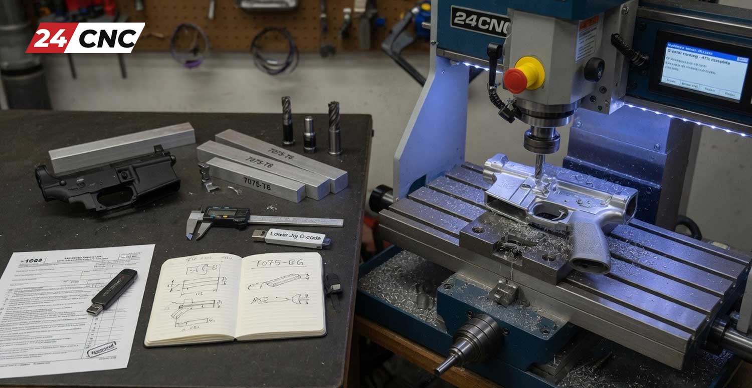
  • 7075-T6 Aluminum: The standard alloy for AR-style upper and lower receivers. It offers high strength-to-weight ratio, excellent yield strength, and superior machinability.
  • 6061-T6 Aluminum: Common for less critical components such as handguards, buffer tubes, and scope rings.
  • 4140 & 416R Stainless Steel: Widely used for rifle barrels, bolt carriers, and pistol slides due to their high tensile strength and resistance to fatigue and erosion.
  • Titanium (Grade 5 / Ti-6Al-4V): Favored for lightweight suppressor baffles, custom receiver components, and high-end fasteners.

Technical Feasibility: What It Takes to Machine Gun Parts

Tolerances and Precision

Firearm mechanisms rely on tight, repeatable interlocks. Critical dimensions—such as pin hole locations, sear engagement faces, and bolt lockup lugs—often require tolerances within ±0.0005 inches (±0.0127 mm). Achieving this level of accuracy requires stable machinery, rigid workholding, accurate tool offsets, and precise closed-loop feedback provided by high-resolution rotary encoders and reliable feedback devices.

Required CNC Equipment and Machine Setup

While basic components can be cut on small benchtop equipment, producing professional-grade firearm parts efficiently requires industrial-grade machinery equipped with robust motion control components.

Machine Type Suitable Gun Parts Key Advantages Primary Limitations
3-Axis CNC Mill Flat receivers, scope mounts, rails, trigger guards Cost-effective, simple programming, widely available Requires multiple setups and repositioning fixtures
4/5-Axis CNC Mill Complex receivers, contoured slides, bolt carriers Single-setup completion, superior surface finish, high precision Higher initial cost, complex CAM programming requirements
CNC Lathe / Turning Center Barrels, muzzle brakes, suppressors, firing pins Ideal for cylindrical symmetry and precise thread cutting Limited to rotational profiles unless equipped with live tooling
Swiss-Type Lathe Pins, small screws, gas pistons, firing pins Extreme speed and precision for micro-diameter long parts High setup complexity, restricted to small bar stock diameters

To maintain high accuracy across continuous production cycles, the motion control architecture must perform flawlessly. Industrial machining centers utilizing reliable control platforms like a Fanuc controller or Siemens controller ensure that complex toolpaths generated in CAM software are translated precisely into mechanical motion without path drift or servo error.

Furthermore, maintaining constant axis torque during heavy roughing passes in tough alloy steels requires fully functional drive systems. Monitoring and maintaining system stability—such as checking a Fanuc drive or Mitsubishi drive—prevents position errors, chatter marks, or thermal drift during critical machining operations.

Workflow: From CAD Design to Finished Component

Manufacturing firearm parts using CNC machinery follows a structured engineering pipeline. Skipping steps or failing to validate toolpaths can lead to broken tooling, damaged workpieces, or unsafe components.

  1. 3D CAD Modeling: The part is designed in CAD software (e.g., SolidWorks, Fusion 360). Critical clearances and material allowances for post-processing treatments (such as hard-coat anodizing or Cerakote) must be factored in.
  2. CAM Programming & Simulation: Toolpaths are created to clear stock efficiently. To understand how code translates to physical machine axis movements, check out our guide on how a CNC controller interprets G-code and M-code. Always run full machine simulations to prevent crashes.
  3. Material Setup & Workholding: The raw stock is clamped using soft jaws, modular vices, or custom fixtures. High precision starts with reliable positioning using manual controls like a responsive MPG handwheel during initial setup and origin zeroing.
  4. Machining Phase: The G-code program executes. High-speed roughing routines remove bulk material, followed by fine finishing passes with ball-nose or flat end mills. Proper coolant flow and thermal management are crucial to prevent dimensional drift.
  5. Quality Assurance & Deburring: Parts are measured using CMM (Coordinate Measuring Machines), optical comparators, or plug gauges. Edge breaks, chamfers, and hand deburring ensure smooth function.
  6. Heat Treatment & Surface Finishing: Steel parts undergo hardening and tempering to achieve proper Rockwell hardness (HRC). Aluminum parts undergo Type III Hardcoat Anodizing for corrosion resistance and wear protection.

Crucial Machine Maintenance for High-Precision Manufacturing

Crucial Machine Maintenance for High-Precision Manufacturing

Because gun components demand minimal variance, machine tool health directly dictates part quality. An unmaintained CNC mill can introduce backlash, poor surface finishes, or out-of-tolerance bore centers.

To avoid costly scrap, machine operators should maintain a strict maintenance schedule. Regularly inspect wear components, clean optical sensors, and maintain axis fans and heat sinks. When electrical faults or drive alarms occur during long machining cycles, knowing how to diagnose and troubleshoot CNC servo amplifier alarms keeps downtime to a minimum and protects workpieces in progress.

Replacing worn internal components, such as checking electrical protection devices like CNC fuses, replacing faulty control cooling cooling fans, or upgrading worn power components like IGBT modules, ensures stable power delivery to high-torque spindle motors during heavy cuts in alloy steel.

Frequently Asked Questions (FAQ)

Is it legal to use a 3D printer or CNC machine to make a gun at home?

In the United States, federal law generally permits an individual to make a firearm at home for personal use, provided they are not legally prohibited from possessing firearms and the firearm complies with local laws (e.g., undetectable firearm rules, state assault weapon bans). However, making a firearm with the intent to sell or give away without an FFL is illegal.

Can I sell non-serialized gun parts made on a CNC machine?

Components that are not legally defined as receivers or frames (such as handguards, scope mounts, rails, trigger shoes, and stocks) can generally be produced and sold commercially without a Federal Firearms License. However, state laws vary, and ITAR compliance may still apply if exporting components.

What is the best CNC machine for making gun parts at home?

For small-scale hobbyist projects involving aluminum components (like lower receivers), desktop or benchtop CNC mills with rigid frames and high-torque spindles are popular. For commercial steel parts or complex slides, industrial 3-axis or 5-axis vertical machining centers (VMCs) are required.

What aluminum alloy should be used for machining lower receivers?

7075-T6 aluminum is the industry standard for AR-style receivers due to its high yield strength (approx. 73,000 psi) and excellent fatigue resistance. 6061-T6 aluminum is easier to machine and cheaper, but offers lower overall tensile strength.

Keep Your CNC Machinery Running with High-Precision Parts

Precision manufacturing demands uninterrupted machine performance. Whether you need replacement servo drives, rotary encoders, or replacement CNC control components, 24CNC provides high-quality parts to keep your shop productive.

Explore CNC Spare Parts Today

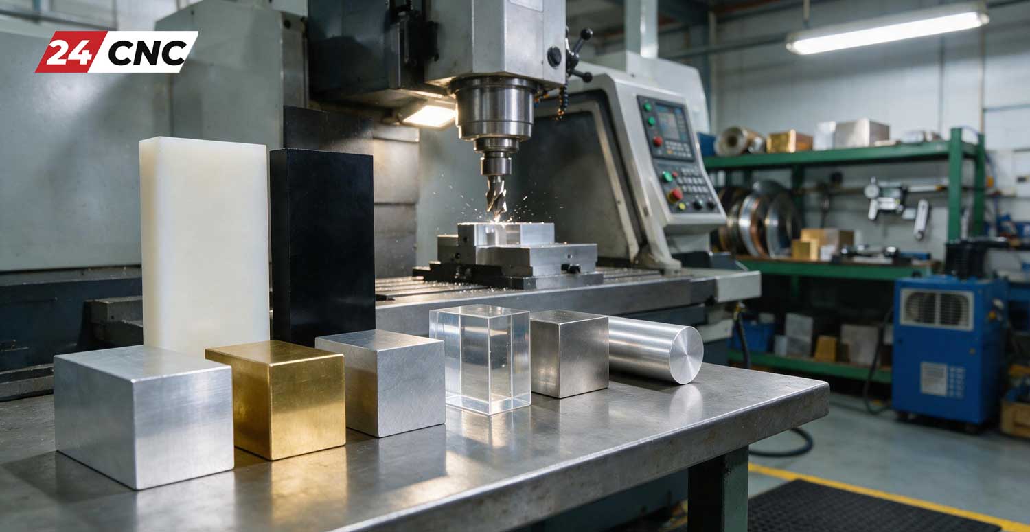
The Most Common Materials Used in CNC Machining

The Most Common Materials Used in CNC Machining

In the expansive world of automated industrial production, writing flawless G-code and selecting the perfect end-mills are only pieces of the puzzle. CNC machining is celebrated for its incredible versatility, allowing operators to carve highly complex, precision parts from solid blocks of virtually any rigid material. Whether you are manufacturing aerospace engine turbines that must withstand immense thermal loads or creating lightweight, aesthetic enclosures for consumer electronics, understanding the most common materials used in CNC machining is the foundation of mechanical engineering.

This exhaustive guide explores the top metals, alloys, and plastics utilized in modern CNC milling and turning centers. We will dissect their mechanical properties, explore their ideal industrial applications, and discuss how different raw materials interact with your machine’s essential components. By the conclusion of this article, you will possess a master-level understanding of material science as it applies to subtractive manufacturing.

Key Factors When Choosing CNC Machining Materials

Before analyzing specific alloys and polymers, it is absolutely vital to comprehend the underlying engineering criteria that dictate material selection. Selecting inappropriate stock can lead to catastrophic tool breakage, poor surface finishes, dimensional inaccuracies, and rapid wear on machine kinematics. When designing parts for CNC machining, engineers must rigorously evaluate the following parameters:

  • Machinability: This metric dictates how easily and rapidly a material can be cut by a cutting tool. Materials with high machinability ratings (like aluminum and brass) require less spindle power, can be machined at higher feed rates, and generate less tool wear. Conversely, tough materials demand rigid setups and put severe strain on the machine’s mechanical axes and servo motors.
  • Mechanical Strength and Hardness: Engineers must calculate the required tensile strength, yield strength, and shear strength based on the part’s end-use application. Material hardness often dictates the cutting speeds and feeds required.
  • Operating Environment and Thermal Limits: Will the component be exposed to highly corrosive chemicals, marine saltwater, or extreme temperatures? Some plastics degrade rapidly above 150^\circ C, while certain aerospace alloys maintain structural integrity even at 800^\circ C.
  • Dimensional Stability and Tolerances: Certain materials warp or release internal stresses during machining. If a part requires strict geometric tolerances (e.g., \pm 0.005 mm), selecting a dimensionally stable material is critical.
  • Weight Restrictions: The aerospace, automotive, and robotics industries heavily prioritize the strength-to-weight ratio. Lighter materials reduce energy consumption in moving assemblies.
  • Cost Feasibility: The final cost is a combination of the raw billet price and the machine time required to shape it. A cheaper raw metal might end up costing more if it takes three times as long to machine and destroys multiple carbide end-mills in the process.

Key Factors When Choosing CNC Machining Materials

The Top Metals and Alloys in CNC Machining

Metals remain the undisputed backbone of heavy industry and structural engineering. They are prized for their high tensile strength, durability, electrical conductivity, and thermal resilience. The following are the most prevalent metals found in professional machine shops globally.

Aluminum Alloys (6061, 7075, 2024)

Aluminum is the undisputed king of CNC machining. It provides a phenomenal balance of excellent machinability, respectable strength, low weight, and cost-effectiveness. It is non-magnetic, naturally forms a protective oxide layer against corrosion, and takes cosmetic anodizing brilliantly.

  • Aluminum 6061-T6: The absolute industry standard for general-purpose machining. It is highly machinable, easy to weld, and relatively inexpensive. It is ubiquitous in automotive components, electronics housings, bicycle frames, and custom prototyping.
  • Aluminum 7075-T6: Renowned for its exceptional strength, which is comparable to many low-carbon steels, 7075 is heavily utilized in aerospace, defense, and high-stress structural applications. However, it is slightly more expensive, less weldable, and slightly less corrosion-resistant than 6061.
  • Aluminum 2024: Frequently used in aerospace applications where high fatigue resistance is required. It machines very well but has poor corrosion resistance, often requiring a clad finish.

Stainless Steel Alloys (304, 316, 416, 17-4 PH)

Stainless steel is explicitly chosen for applications requiring high structural integrity combined with exceptional resistance to rust, oxidation, and corrosive environments. Machining stainless steel is notably more difficult than aluminum; it tends to work-harden rapidly, requiring highly rigid machine setups, heavy coolant flow, and premium tooling.

  • Stainless Steel 304: The most common austenitic stainless steel. It offers excellent corrosion resistance and formability, making it the standard for food processing equipment, kitchenware, and industrial piping.
  • Stainless Steel 316: The addition of molybdenum gives 316 superior resistance to chlorides (like saltwater) and harsh industrial chemicals. It is the mandatory choice for marine hardware, pharmaceutical processing, and medical devices.
  • Stainless Steel 416: A martensitic, free-machining grade of stainless steel. The addition of sulfur makes it much faster to cut than 304/316, though it sacrifices a degree of corrosion resistance. Ideal for gears, shafts, and threaded fasteners.
  • 17-4 PH Stainless Steel: A precipitation-hardening alloy that offers immense strength and hardness alongside excellent corrosion resistance. Heavily used in aerospace and the petrochemical industry.

Titanium (Ti-6Al-4V / Grade 5)

Titanium is highly sought after for its legendary strength-to-weight ratio and superb, naturally occurring corrosion resistance. Furthermore, it is biologically compatible (non-toxic to the human body), making it the premier choice for medical implants (like hip replacements) and premium aerospace components. However, titanium is notoriously difficult to machine. It has very low thermal conductivity, meaning heat does not dissipate into the chip; instead, it concentrates at the cutting edge of the tool. This requires slow cutting speeds, aggressive coolant strategies, and robust machine mechanics, putting high electrical demand on the machine’s power supplies and drive systems.

Brass (C360) and Copper (C101)

Copper alloys are primarily utilized for their electrical and thermal conductivity, as well as cosmetic appeal.

  • Brass C360 (Free Machining Brass): Brass is arguably the easiest and fastest metal to machine on a CNC router or lathe. It yields extremely low friction, excellent electrical conductivity, and a beautiful golden finish. Its high machinability means it causes almost zero wear on cutting tools. It is used extensively for plumbing fittings, electrical terminals, and musical instruments.
  • Copper C101 (Oxygen-Free Copper): Offers unparalleled electrical and thermal conductivity. It is highly ductile, which can make it “gummy” during machining, requiring specific sharp tooling geometries to prevent chip welding. Used heavily in heat sinks, electrical bus bars, and telecommunications.

Carbon Steels and Alloy Steels (1018, 4140)

When high strength is required without the premium cost of stainless steel or titanium, plain carbon and alloy steels are utilized.

  • 1018 Mild Steel: A low-carbon steel that offers good weldability and machinability at a very low cost. It is the go-to metal for basic structural components, jigs, and fixtures where corrosion is not a primary concern.
  • 4140 Alloy Steel: A chromium-molybdenum steel known for its exceptional toughness and fatigue strength. It is often machined in its annealed state and subsequently heat-treated to achieve high hardness. Commonly used in automotive axles, crankshafts, and heavy machinery gears.

The Top Metals and Alloys in CNC Machining


Top Plastics Used in CNC Machining

While heavy industry is dominated by metals, engineering plastics are incredibly vital in CNC machining for producing components that require low weight, electrical insulation, chemical resistance, or RF transparency. Machining plastics requires very sharp tools, aggressive chip evacuation, and careful heat management to prevent the material from melting and smearing along the cutting path.

POM (Delrin / Acetal)

Polyoxymethylene (POM), widely recognized by the DuPont brand name Delrin, is the undisputed king of CNC machined plastics. It perfectly bridges the gap between metal and ordinary plastics, offering remarkable stiffness, low surface friction, and excellent dimensional stability. Because it machines into crisp, clean chips (unlike many stringy plastics), it is highly favored by machinists. It is ideal for mechanical gears, sliding bearings, and structural insulators where metal is too heavy.

PEEK (Polyether ether ketone)

PEEK is a high-performance engineering thermoplastic reserved for the most demanding applications. It retains its mechanical strength and stiffness at extremely high temperatures (withstanding continuous use up to 250^\circ C) and resists a vast array of corrosive organic and aqueous environments. PEEK is frequently utilized as a lightweight substitute for metal in aerospace, medical sterilization equipment, and oil/gas extraction. Be warned: PEEK is one of the most expensive plastics to purchase and machine.

Polycarbonate (PC)

Polycarbonate is renowned for its outstanding impact resistance (virtually unbreakable) and optical transparency. While often injection molded for mass production, it is frequently CNC machined for functional prototypes, optical lenses, automotive light housings, and safety blast shields. Machining PC requires careful feed rate management; excessive heat can cause internal stress cracking, ruining the part’s structural integrity.

Nylon (Polyamide)

Nylon is a highly versatile plastic known for its toughness, impact resistance, and excellent wear properties. Nylon 6/6 is the most common grade machined. It is frequently used for wear pads, custom sprockets, and low-speed bearings. A notable drawback of Nylon is that it absorbs moisture from the environment, which can cause slight dimensional swelling over time.

PTFE (Teflon)

Polytetrafluoroethylene (PTFE), widely known as Teflon, boasts one of the lowest coefficients of friction of any solid material. It is completely chemically inert and can operate at high temperatures. However, PTFE is quite soft and has poor dimensional stability, making it difficult to hold tight tolerances during machining. It is mostly used for specialized chemical gaskets, seals, and non-stick surfaces.

Technical Comparison Table: CNC Material Properties

To assist in rapid decision-making, below is a comprehensive technical matrix comparing the most common CNC materials based on their machinability, relative cost, and defining characteristics.

Material Classification Machinability Rating Relative Cost (Raw) Primary Strengths Common Industrial Applications
Aluminum 6061-T6 High Low Lightweight, excellent strength-to-weight, anodizes well General electronics enclosures, robotics, auto parts
Stainless Steel 316 Medium-Low Medium-High Exceptional resistance to chlorides, high strength Surgical tools, marine hardware, chemical tanks
Titanium (Grade 5) Low Very High Extreme strength-to-weight, biocompatible, corrosion-proof Aerospace turbines, orthopedic implants
Brass (C360) Very High Medium Low friction, highly machinable, conductive Fluid fittings, electrical contacts, custom valves
POM (Delrin / Acetal) High Low High stiffness, fantastic dimensional stability Plastic gears, bearings, electrical insulators
PEEK Medium Very High Maintains properties up to 250^\circ C, chemically inert High-heat aerospace insulators, pump wear rings

The Impact of Material Selection on Machine Hardware

It is imperative for workshop owners to recognize that the materials they choose to process have a direct and measurable impact on the lifespan and maintenance schedule of their CNC machinery. Machining tough, high-tensile materials like Inconel, Titanium, or hardened tool steels generates immense cutting forces. These forces translate into intense vibrations and thermal loads that travel straight through the tool holder and into the machine’s structural castings.

This continuous stress puts severe strain on spindle bearings, ball screws, and the intricate electronic control systems governing the axes. If your shop routinely cuts difficult alloys, you must ensure that components like your amplifiers and inverters are correctly tuned and operating at optimal efficiency to handle the fluctuating torque demands. If your machine begins to stall, fault out, or struggle to maintain rigid tapping cycles in hard metals, it is highly likely that your electronic drives require inspection, maintenance, or an upgrade to handle the heavy-duty material load.

The Impact of Material Selection on Machine Hardware

Frequently Asked Questions (FAQ)

What is the most cost-effective material for CNC prototyping?

For the vast majority of projects, Aluminum 6061 and engineered plastics like POM (Delrin) or ABS are the most cost-effective choices. Their high machinability reduces the spindle time required (lowering hourly labor costs) and minimizes wear and tear on expensive carbide cutting tools, thereby keeping total production overhead exceptionally low.

Can standard lightweight CNC routers cut hard metals like Titanium or Stainless Steel?

Generally, no. While the G-code logic remains identical, successfully cutting high-tensile metals requires a highly rigid, heavy cast-iron machine frame to absorb vibration. It also demands high-torque spindles and specialized high-pressure flood cooling systems. Lighter, hobby-grade routers or basic gantry machines lack this rigidity; they will chatter aggressively, instantly shatter cutting tools, and potentially damage their internal drive electronics when attempting to machine materials like Titanium.

Why is PEEK plastic so extraordinarily expensive?

PEEK raw material is inherently expensive due to the highly complex, multi-stage chemical synthesis required to manufacture it. Furthermore, while it cuts cleanly, it requires incredibly precise temperature control, specialized annealing processes to prevent warping, and razor-sharp tooling to avoid inducing internal stresses. This increases both the raw material cost and the overall machining complexity.

Conclusion

Mastering material selection is a fundamental requirement for anyone involved in modern manufacturing. As demonstrated throughout this guide, the choice between an aerospace-grade aluminum, a chemically resistant stainless steel, or a high-performance thermoplastic like PEEK dictates every subsequent step in the manufacturing process. From configuring cutting speeds and feeds to determining the required rigidity of the milling center, material properties govern the physics of machining. By carefully weighing factors such as machinability, thermal resistance, mechanical strength, and economic feasibility, engineers can ensure that their designs are not only functionally superior but also optimized for cost-effective and efficient production.

Maintain Your CNC Machine’s Peak Performance Under Heavy Loads

Machining tough alloys and high-performance plastics can eventually take a toll on your equipment’s electronics and mechanical drives. Keep your production line running flawlessly with high-quality, reliable replacement components for your CNC control systems.


Explore Premium CNC Replacement Parts Today

How to Start a Small CNC Business from Your Garage

How to Start a Small CNC Business from Your Garage

The modern manufacturing landscape has shifted dramatically. Decades ago, launching a machining business required massive capital, thousands of square feet of industrial floor space, and heavy-duty 3-phase electrical grids. Today, the democratization of technology means that learning how to start a small CNC business from your garage is not just a pipe dream—it is a highly viable, scalable, and profitable reality.

Whether you are an experienced machinist tired of the corporate grind, or a passionate hobbyist looking to monetize your workshop, a garage-based CNC (Computer Numerical Control) business offers an incredible entry point. With the right machine, a solid understanding of CNC machining principles, and a strategic approach to finding your niche, you can turn raw aluminum, wood, or plastics into high-margin products.

However, scaling from a hobbyist tinkering on weekends to a reliable production shop requires careful planning. You need to consider power requirements, tooling, software, and most importantly, machine reliability. In this comprehensive guide, we will walk you through the exact steps to launch your garage CNC business, upgrade your equipment, and secure your first paying customers.

Crafting Your Business Plan: Finding Your Profitable Niche

Crafting Your Business Plan: Finding Your Profitable Niche

The biggest mistake new garage CNC owners make is trying to be a “job shop” for everyone. When you are operating out of a 400-square-foot residential garage, you cannot compete on volume with massive overseas factories or large local industrial machine shops. Instead, your competitive advantage is specialization, customizability, and speed.

Before you buy a machine, you must identify what you want to make. Making money selling CNC machined parts requires targeting specific industries:

  • The Automotive/Motorsports Niche: Custom brackets, dashboard panels, shift knobs, and specialized engine components machined from 6061 aluminum. Enthusiasts pay a premium for custom, low-volume billet parts.
  • Woodworking & Signage: Using a CNC router to create custom topographical maps, engraved wooden signs for local businesses, or bespoke furniture components.
  • Prototyping for Local Inventors: Many product designers need rapid prototypes in Delrin (acetal) or aluminum before committing to expensive injection molds. Offering fast turnaround prototyping is highly lucrative.
  • EDC (Everyday Carry) Gear: Custom knives, multi-tools, titanium keychains, and fidget toys have a massive online market and require very little raw material space.

Choosing the Right Machine and Prepping Your Garage

Your business model dictates your machine. A 4×8 foot CNC router is excellent for cabinetry but useless for high-tolerance titanium parts. Conversely, a rigid vertical machining center (VMC) will slice through steel but has a tiny work envelope.

A. Understanding Axis Configuration

For most garage startups, a standard 3-axis machine (X, Y, and Z) is the standard. It is affordable and easy to learn. However, if you plan to machine complex aerospace or medical parts, you might need to look into 4-axis or 5-axis capabilities. Understanding CNC machine axes (3-axis vs 5-axis) early on will prevent you from outgrowing your machine within the first year.

B. Power, Noise, and Air Supply

Residential garages are not built for industrial manufacturing. You must address the “Big Three” infrastructure hurdles:

  • Electrical Power: Most industrial CNC machines require 3-phase, 220V power. Houses only have single-phase power. You will likely need to purchase a Rotary Phase Converter (RPC) or choose a “prosumer” CNC designed to run on single-phase 220V.
  • Air Compressors: CNC mills require constant, clean, dry compressed air for tool changers and spindle clearing. Buy the quietest, highest-capacity rotary screw or scroll compressor you can afford. Noise complaints from neighbors will shut your business down faster than anything else.
  • Climate Control: Extreme temperature fluctuations in a garage will expand and contract your machine’s cast iron frame, destroying your precision. Insulate your garage doors and install a mini-split AC system.

Upgrading Your Machine for Reliability: Essential Parts

Upgrading Your Machine for Reliability: Essential Parts

Many garage entrepreneurs start by purchasing used, older CNC machines (like legacy Haas, Fadal, or Fanuc-controlled mills) to save money. While the cast iron on these older machines is excellent, the electronics are often failing. To ensure you don’t miss customer deadlines due to machine downtime, you must be prepared to retrofit and replace key electrical components.

The Control System & Servos

The brain of your machine is its Control System. Older controllers can be painfully slow when processing complex 3D toolpaths. Upgrading to a modern controller or ensuring your current one has healthy boards is crucial. Furthermore, replacing old, lost-step prone stepper motors with closed-loop Servo Motors will vastly improve your surface finishes and part accuracy.

Manual Pulse Generators (MPG Handwheels)

In a garage shop where you do a lot of custom, one-off prototyping, you will spend significant time manually jogging the machine to set work offsets. A high-quality MPG Handwheel is an absolute necessity for safe, precise setup without having to lean over your machine to reach the main panel.

Knowing where to buy high-quality CNC parts online is vital. When a power supply fails or an encoder breaks on a Friday night, having a reliable supplier like 24cnc.com ensures you are back up and running by Monday.

The Software Stack: CAD, CAM, and G-Code

Your machine is only as smart as the instructions you give it. To run a modern CNC business, you need to master the digital workflow:

  1. CAD (Computer-Aided Design): This is where you design your parts. Learning how to design parts for CNC machining is the first step. Software like Fusion 360, SolidWorks, or FreeCAD allows you to create precise 3D models. Always keep tool clearance and internal radii in mind when designing.
  2. CAM (Computer-Aided Manufacturing): CAM software translates your 3D CAD model into toolpaths. You will define the tools (endmills, drills, chamfer tools), speeds, feeds, and the order of operations.
  3. G-Code: The CAM software outputs a language called G-Code. Understanding what G-code is is mandatory. While the software writes the bulk of it, as a machinist, you need to be able to read the raw code at the machine to verify feed rates, fix small errors, and prevent catastrophic crashes.

Garage CNC Machine Tiers: A Comparison

Not sure what machine category fits your budget and garage limitations? Review our breakdown below:

Machine Tier Avg. Investment Power Requirement Ideal Materials Best Business Niche
Desktop / Hobby Router $1,500 – $4,000 Standard 110V Wood, Plastics, Foam Etsy signs, simple wood crafts
Prosumer CNC Mill (e.g., Tormach/Syil) $10,000 – $25,000 Single-Phase 220V Aluminum, Brass, Light Steel Auto parts, EDC gear, prototyping
Used Industrial VMC (e.g., Haas Mini Mill) $15,000 – $40,000 3-Phase 220V (Needs Converter) Stainless Steel, Titanium, Aluminum Production runs, aerospace, medical

Preventative Maintenance: Keeping the Spindle Turning

Preventative Maintenance: Keeping the Spindle Turning

If your spindle isn’t turning, you aren’t making money. In a one-person garage shop, you are the CEO, the janitor, and the lead maintenance technician. Establishing a strict CNC machine maintenance checklist from day one is non-negotiable.

Check your way lube levels daily. Clean the coolant tank monthly to prevent bacteria buildup (which causes horrible smells in your garage and rusts your machine). Keep a stockpile of critical replacement parts on hand—fuses, limit switches, and standard sensors—so a minor electrical hiccup doesn’t ruin your production week.

Frequently Asked Questions (FAQ)

Is starting a CNC business actually profitable?

Yes, highly profitable, provided you find a niche. The profit margins on raw materials (like billet aluminum) compared to the finished machined product can easily exceed 300% to 500%. However, your true cost is time and tooling, which is why optimizing your CAD/CAM programs for faster cycle times is crucial for profitability.

Do I need to be a machinist to start?

No, but a steep learning curve exists. Many successful modern garage shop owners started as graphic designers, engineers, or hobbyists. Modern conversational controls and highly intuitive CAM software have lowered the barrier to entry significantly. Be prepared to ruin some parts and break tools while you learn.

Can I run an industrial CNC on standard residential power?

Generally, no. Industrial CNC machines require 3-phase power. You will need to wire a dedicated 220V 50A or 100A sub-panel in your garage and install a Phase Perfect (digital) or Rotary Phase Converter to generate the 3rd leg of power required by the machine’s spindle and servos.

What is the most common reason garage CNC businesses fail?

Failing to market properly and attempting to compete on price rather than quality. You cannot out-price large overseas factories. Garage shops fail when they take low-paying, high-volume jobs instead of focusing on high-margin, specialized, low-volume orders where communication and quality control justify higher prices.

Keep Your Garage Shop Running at Peak Performance

Starting a CNC business is just the beginning. As you take on paying clients, machine downtime becomes your biggest enemy. From replacement servomotors and control boards to essential MPGs and cables, 24cnc.com is your trusted partner for high-quality CNC spare parts.

Explore Our CNC Parts Inventory

Introduction to CNC Programming for Absolute Beginners

Introduction to CNC Programming for Absolute Beginners

Stepping into the world of industrial automation and modern machining can feel incredibly overwhelming at first glance. Watching massive, multi-ton milling machines and lathes carve out intricate geometries from solid blocks of titanium or steel with micron-level precision is nothing short of mesmerizing. However, behind the roar of the spindles and the spray of the coolant lies a silent, highly logical orchestrator: CNC programming. If you are an aspiring machinist, a manufacturing engineer, a workshop owner, or simply an enthusiast looking to break into this lucrative field, understanding how to communicate with these machines is your first and most crucial step.

In this comprehensive pillar page, we will demystify the language of industrial manufacturing. We will start from the absolute basics—assuming you have zero prior experience—and gradually build your knowledge base. By the end of this guide, you will understand how machines perceive space, how to read and write basic code, and the differences between manual programming and modern software-driven approaches.

What is CNC Programming and Why is it the Future of Manufacturing?

The acronym CNC stands for Computer Numerical Control. Before the advent of computers, machinists operated manual mills and lathes using handwheels, relying heavily on their physical skill, extreme focus, and years of muscle memory to cut parts to size. The introduction of CNC technology revolutionized this process. Instead of a human turning a wheel, servo motors and drive systems move the machine’s axes. But these motors need instructions—they need to know exactly how far to move, at what speed, and in what direction. For a broader overview of this evolution, we highly recommend reading our foundational article, What is CNC Machining?.

CNC programming is the art and science of creating these highly specific instructions. You are essentially translating a 3D physical object into a sequence of alphanumeric codes that a machine’s computer brain can interpret. Learning this skill is highly rewarding for several reasons:

  • Unmatched Precision and Repeatability: A well-written program can produce ten thousand identical parts with zero deviation, something impossible for a manual machinist.
  • Career Growth: Skilled CNC programmers are highly sought after in aerospace, automotive, medical device manufacturing, and defense industries.
  • Creative Freedom: If you can program it, you can make it. It allows workshop owners to prototype rapidly and bring complex designs to life.

The Foundation: Mastering the Cartesian Coordinate System

The Foundation: Mastering the Cartesian Coordinate System

Before you even think about writing a single line of code, you must completely rethink how you view physical space. CNC machines are blind; they do not have eyes to see the raw material. Instead, they rely entirely on a mathematical grid known as the Cartesian Coordinate System. If you remember your high school geometry, you are already halfway there.

In a standard 3-axis CNC vertical milling machine, space is divided into three primary linear axes:

  • The X-Axis: This represents the horizontal movement of the machine table (left and right relative to the operator).
  • The Y-Axis: This represents the depth movement of the table (forward and backward, moving toward or away from the operator).
  • The Z-Axis: This is arguably the most critical axis for safety. It represents the vertical movement of the spindle (the rotating cutting tool) moving up and down. Moving down (Z-negative) cuts into the material, while moving up (Z-positive) retracts the tool to safety.

Modern manufacturing often requires more complex movements, leading to the development of 4-axis and 5-axis machines, which introduce rotational axes (A, B, and C). To dive deeper into how these advanced machines operate, check out our guide on Understanding CNC Machine Axes (3-Axis to 5-Axis).

Machine Zero vs. Work Zero

A crucial concept for beginners to grasp is the difference between zero points. Machine Zero (Home Position) is a fixed point designated by the manufacturer, usually at the extreme positive limits of all axes. However, programming from Machine Zero is a nightmare. Instead, we use Work Zero (Part Zero). This is a custom origin point (X0, Y0, Z0) that the operator sets on the actual raw material (the billet). All your programmed coordinates will be relative to this Work Zero, making the math significantly easier.

The Language of Manufacturing: Decoding G-Code

When we talk about “CNC Programming,” we are primarily talking about G-Code. This is the alphanumeric language that dictates the physical geometry of the toolpath. For a supplementary beginner’s perspective, our post An Introduction to G-Code for Beginners is a great companion piece. Below is a detailed breakdown of the most essential G-Codes every absolute beginner must memorize.

The Primary Motion Codes

  • G00 (Rapid Positioning): This tells the machine to move to a specific coordinate as fast as its motors will allow. Crucial rule: Never use G00 when the cutting tool is engaged with the material. It is strictly for moving through the air.
  • G01 (Linear Interpolation): This is your primary cutting code. It tells the machine to move in a straight line at a specific, controlled speed (known as the Feed Rate).
  • G02 (Circular Interpolation Clockwise): Used for cutting arcs and circles in a clockwise direction. It requires you to specify the center of the arc using I and J coordinates or an R (radius) value.
  • G03 (Circular Interpolation Counter-Clockwise): The exact opposite of G02; used for counter-clockwise arcs.

Positioning and Unit Codes

  • G20 and G21: G20 sets the machine to read coordinates in Inches (Imperial), while G21 sets it to Millimeters (Metric). Mixing these up will result in catastrophic part failures.
  • G90 (Absolute Positioning): The machine reads all coordinates based on the single Work Zero point. If you command X10, the tool goes to the position 10 units away from zero.
  • G91 (Incremental Positioning): The machine reads coordinates based on its current position. If the tool is at X5, and you command X10 in G91 mode, it will move an additional 10 units to end up at absolute position X15.

Taking Control with M-Codes and Auxiliary Commands

Taking Control with M-Codes and Auxiliary Commands

While G-Codes handle the geometry (where the tool goes), M-Codes (Miscellaneous Codes) act as the hardware switches. They turn physical components of the machine on and off. Furthermore, other letters like S, F, and T complete the program. To understand how the machine’s brain processes these, read about What a CNC Controller Interprets.

  • M00 (Program Stop): Forces the machine to stop everything and wait for the operator to press the Start button. Useful for mid-operation inspections.
  • M03 and M04 (Spindle Control): M03 turns the spindle on in a clockwise (Forward) direction, which is standard for most cutting tools. M04 turns it on counter-clockwise (Reverse), usually used for specialized tapping operations.
  • M05 (Spindle Stop): Halts the rotation of the spindle.
  • M06 (Tool Change): Commands the machine’s Automatic Tool Changer (ATC) to swap the current tool for a new one.
  • M08 and M09 (Coolant Control): M08 turns the flood coolant pump on to lubricate the cut and clear chips. M09 turns the coolant off.
  • M30 (End of Program): Signals that the machining process is complete. It stops the spindle, turns off coolant, and rewinds the code back to the very first line for the next part.

Alongside M-Codes, we use S-Codes for Spindle Speed (e.g., S2500 means 2500 Revolutions Per Minute) and F-Codes for Feed Rate (e.g., F500 means the tool will move through the material at 500 millimeters per minute). T-Codes select the tool number (e.g., T01 prepares Tool #1).

The Brain of the Operation: Understanding CNC Controllers

You can write the most perfect G-Code in the world, but without a controller to interpret it, it is just text on a screen. The CNC Controller is an industrial computer wired directly to the machine’s servos, encoders, and relays. While the foundation of G-Code (ISO standard) is universal, different controller brands have unique “dialects,” especially when it comes to complex operations like Canned Cycles (pre-programmed drilling or tapping sequences).

Two of the absolute giants in the industrial world are Fanuc and Siemens. Fanuc is incredibly robust, reliable, and holds a massive market share globally. Siemens offers highly advanced, user-friendly conversational programming interfaces on their Sinumerik platforms. If you are building, retrofitting, or repairing a machine, sourcing high-quality control components is vital. You can explore our extensive inventory of Fanuc Controller parts or browse our high-end Siemens automation equipment directly in our shop.

Manual Programming vs. Modern CAD/CAM Software

A common question from absolute beginners is: “Do I really have to type thousands of lines of code by hand?” The answer is a resounding no, though understanding how to read those lines remains critical. Today, the industry is split between manual coding for simple tasks and CAD/CAM software for complex geometries. To visualize this modern workflow, review our article on How CNC Parts are Made: From 3D Model to Finished Product.

Feature / Metric Manual Programming (By Hand) CAD/CAM Software Programming
Ideal Application Simple 2D profiles, bolt hole circles, facing operations, and quick on-the-fly shop floor edits. Complex 3D organic shapes, mold making, aerospace components, and simultaneous 5-axis machining.
Code Generation Speed Very slow. Requires the programmer to calculate trigonometry and cutter coordinates manually. Extremely fast. Software algorithms can generate millions of lines of optimized code in seconds.
Risk of Human Error High. A single misplaced decimal point (e.g., X10 vs X10.0) can cause a catastrophic machine crash. Low. High-end CAM software includes digital twin simulation to verify toolpaths before actual cutting.
Prerequisite Skills Deep memorization of G & M codes, strong math skills, and intimate knowledge of the controller. Proficiency in 3D modeling (CAD) and understanding of machining strategies, tooling, and feed/speed formulas.

Pro-Tip for Beginners: Do not skip straight to CAM software. If you do not understand the raw G-Code, you will not know how to troubleshoot when the CAM software inevitably generates an inefficient or dangerous toolpath. Learn manual coding first; it will make you a vastly superior CAM programmer later.

The Anatomy of a CNC Program Block

The Anatomy of a CNC Program Block

Let’s put everything we’ve learned together. In CNC programming, a single line of code is referred to as a Block. The machine reads these blocks sequentially, one by one, from top to bottom. Here is a breakdown of a very simple, standardized program block sequence:

%
O1001 (PROGRAM NAME – SIMPLE DRILL)
N10 G90 G21 G17 G40 G80 (Safety Block: Absolute, Metric, XY Plane, Cancel Comp, Cancel Cycles)
N20 T01 M06 (Call Tool Number 1 and execute Tool Change)
N30 S2000 M03 (Turn Spindle ON Clockwise at 2000 RPM)
N40 G00 X25.0 Y25.0 (Rapid move over the first hole location)
N50 G43 H01 Z10.0 M08 (Apply Tool Height Offset 1, rapid to 10mm above part, Coolant ON)
N60 G01 Z-5.0 F150 (Feed down 5mm into the material at 150 mm/min)
N70 G00 Z10.0 (Rapid retract out of the hole to safe clearance)
N80 G91 G28 Z0 M09 (Return to Z Home Position, Coolant OFF)
N90 M30 (End of Program and Rewind)
%

Notice line N50. It contains G43 H01. This is incredibly important. G43 tells the machine to activate Tool Length Compensation. Because every tool (a drill, an endmill, a face mill) has a different physical length, the machine needs to offset the Z-axis by the exact length of that specific tool (stored in the controller’s register under H01). Without G43, the machine would plunge the spindle directly into the table, causing a devastating crash.

Crucial Best Practices & Avoiding Costly Mistakes

In web development, a bad line of code throws an error on a screen. In CNC programming, a bad line of code throws a 5-pound chunk of steel across the room or shatters a $50,000 spindle. Safety and verification are paramount.

  1. Beware the Decimal Point: On older Fanuc and Haas controllers, omitting a decimal point can be disastrous. If you want to move 10 millimeters, you must write X10.0. If you write X10, the controller might read it in internal machine units (microns), moving the machine only 0.01mm. Always double-check your decimals!
  2. Always Run a Simulation: Use the controller’s onboard graphical verification tool to trace the toolpath on the screen before pressing Cycle Start.
  3. Cut Air First (Dry Run): A “Dry Run” means running the program with the actual raw material removed from the vise, or running the program with the Z-axis offset artificially high. This allows you to watch the physical motions of the machine in real space without risking a tool collision.
  4. Keep One Hand on the Feed Hold: When running a new, unproven program for the very first time, the operator should have their finger hovering over the Feed Hold (Pause) or Emergency Stop (E-Stop) button, ready to react if the machine moves unexpectedly.

Frequently Asked Questions (FAQ) About CNC Programming

1. Do I need to be a math genius to learn CNC programming?

Absolutely not. While an advanced understanding of trigonometry is helpful for manual programming of complex angles, basic arithmetic and a solid grasp of Cartesian geometry (X, Y, Z coordinates) are entirely sufficient to get started. Modern CAM software handles all the heavy mathematical lifting and complex calculations for you.

2. How long does it realistically take to learn?

You can learn the basic G-Codes and write simple manual programs (like drilling a bolt circle or facing a square block) in just 2 to 4 weeks of dedicated study. However, mastering advanced CAM software, understanding feed and speed metallurgy, and becoming an expert programmer who can optimize cycle times takes years of hands-on, practical experience.

3. What is the best software for an absolute beginner to start with?

If you want to practice raw G-Code safely without a machine, software like CNC Simulator Pro or NC Viewer (browser-based) is excellent. When you are ready to step up to CAD/CAM, Autodesk Fusion 360 is highly recommended for beginners due to its massive community, vast array of free tutorials on YouTube, and integrated CAD-to-CAM workflow. In industrial environments, Mastercam and SolidCAM are industry standards.

4. Will code written for one machine work perfectly on another?

Not always! While the core ISO G-Codes (like G00, G01, M03) are nearly universal across the globe, specific Canned Cycles (like G83 for peck drilling), macro variables, and specialized M-Codes vary dramatically between manufacturers (e.g., Haas vs. Siemens). You must always run your CAM program through a specific Post-Processor designed exactly for your machine’s make and model.

Final Thoughts on Your CNC Journey

Learning CNC programming is like learning to play a musical instrument. You start by learning the individual notes (G-Codes and M-Codes), then you learn how to string them together into simple chords (programming blocks), and eventually, with practice and software tools, you will be conducting entire symphonies of metal removal. Focus intensely on the fundamentals of the Cartesian coordinate system, prioritize safety over speed, and never stop learning. The manufacturing industry is constantly evolving, and a solid foundation in programming will ensure you evolve right alongside it.

Need to Upgrade or Repair Your CNC Equipment?

Whether you are an absolute beginner assembling your first desktop router or an experienced industrial manufacturer maintaining a fleet of 5-axis machining centers, your code is only as good as the hardware executing it. At 24CNC, we stock an exhaustive inventory of premium replacement parts, advanced controllers, servo drives, and precision motors—all guaranteed for authenticity and performance.

Shop Premium CNC Parts Online Today

What is G-Code? A Beginner's Introduction

What is G-Code? A Beginner’s Introduction

In the advanced world of industrial automation and manufacturing, lathes and milling machines cannot understand our intentions on their own. They require a common language to move, cut, and create complex parts. This common language, acting as the bridge between an engineer’s mind and the machine’s mechanical arm, is called G-Code. Whether you have just entered the world of CNC machining or want to gain a deeper understanding of how these powerful machines operate, knowing G-Code inside and out is your first and most crucial step.

In this comprehensive article, we will explain in simple yet highly technical terms what G-Code is, how it is structured, and how it differs from other control codes. Join us as we journey into the beating heart of machine tool programming.

Introduction to the Machining World: The Language of CNC Machines

Computer Numerical Control (CNC) machines require highly precise, millimeter-accurate instructions to perform their tasks. When an engineer creates a beautiful, intricate part in 3D CAD (Computer-Aided Design) software, that model means absolutely nothing to a CNC machine until it is translated into a set of coordinates and movement commands. This translation process is typically handled by CAM (Computer-Aided Manufacturing) software, resulting in a text file containing thousands of lines of code known as G-Code.

G-Code essentially tells the machine how fast the cutting tool should move, what coordinates (such as X, Y, Z) it should travel to, what path it should take, and when to start or stop the material removal process. Understanding this language is vital for operators and programmers, not only for producing critical parts but also for troubleshooting and optimizing machining time.

Introduction to the Machining World: The Language of CNC Machines

What Exactly is G-Code and How Does it Work?

The term G-Code stands for Geometry Code. Originally developed in the 1950s by the MIT Servomechanisms Laboratory, it is now globally recognized as the industrial standard (RS-274). G-codes directly affect the geometry of movement. In other words, wherever there is a need for linear movement, circular motion, drilling, or positioning, G-Code is involved.

Structure of a Program Line (Block) in G-Code

A CNC program consists of multiple lines, with each line referred to as a “Block”. The machine’s controller (such as the popular Fanuc or Siemens controllers) reads and executes these blocks line by line. The standard structure of a block usually looks like this:

  • N (Line Number): For example, N100. Used purely for program organization and readability.
  • G (Geometry Code): The main movement command. For example, G01 for linear interpolation.
  • X, Y, Z (Coordinates): Defines the tool’s position along the CNC machine axes.
  • F (Feed Rate): The speed at which the tool moves while cutting (e.g., F500).
  • S (Spindle Speed): The rotational speed of the tool or workpiece in Revolutions Per Minute (RPM).
  • T (Tool Number): Used to call a specific tool from the automatic tool changer (e.g., T01).
  • M (Miscellaneous Codes): Used to control the machine’s auxiliary functions.

For example, the block N05 G01 X50.0 Y25.0 F200 tells the machine: “On line 5, use linear movement at a feed rate of 200 to travel to coordinates X=50.0 and Y=25.0.”

What is the Difference Between G-Code and M-Code?

One of the most frequently asked questions among beginners is the difference between G-codes and M-codes. To answer this, we must look at the nature of the machine’s operations. As mentioned earlier, G-codes are responsible for movement and geometry. They dictate the toolpath. However, a CNC machine needs to do more than just move; for instance, it needs to turn on the coolant system, start the spindle rotation, or stop completely at the end of a cycle.

This is where M-codes, or Miscellaneous Codes (sometimes called Machine Codes), come into play. M-codes are responsible for hardware control and auxiliary functions. For example, the code M03 issues the command to turn on the spindle in a clockwise direction, while M08 turns on the coolant pump. To read more on this topic, you can check out our comprehensive article on how a CNC controller interprets G-Code and M-Code.

What is the Difference Between G-Code and M-Code?

List of the Most Common G-Codes in CNC Machining

There are hundreds of different G-codes, and they can vary slightly depending on the machine type (lathe, mill, laser, etc.) and the controller. However, certain codes are entirely standard and essential. In the table below, we review the most frequently used codes:

Code Name (G-Code) Function & Technical Description Command Group
G00 Rapid Traverse – Moving the tool at maximum machine speed without cutting. Motion
G01 Linear Interpolation – Moving the tool in a straight line at a specified feed rate (F) for cutting. Motion
G02 Circular Interpolation Clockwise (CW). Motion
G03 Circular Interpolation Counter-Clockwise (CCW). Motion
G20 / G21 Set measuring units (G20 for Inches, G21 for Metric/Millimeters). Setup
G90 / G91 Set coordinate system (G90 for Absolute positioning, G91 for Incremental positioning). Setup

The Role of CAM Software in G-Code Generation

In the old days, engineers had to manually write all lines of G-Code on paper using complex mathematical calculations and then transfer them to the machine via punched tape! Today, however, thanks to technological advancements and the presence of powerful CAM (Computer-Aided Manufacturing) software like Mastercam, PowerMill, and Fusion 360, this process has been completely transformed.

These software programs take the 3D model and, based on parameters set by the programmer (such as workpiece material, tool type, machining strategy, and cutting speeds), simulate the toolpath. Once the path is approved, a unit called the Post Processor comes into play. The post processor’s job is to translate the toolpath into G-codes that are specifically understood by your machine’s controller. Having a highly accurate post processor ensures that the generated codes won’t cause errors or crashes on your specific machine.

Industrial Controllers and How They Interpret G-Code

Not all CNC machines interpret G-Code in exactly the same way. The brain of any CNC machine is its controller, which is considered one of the essential components of CNC machines. Various global brands manufacture these controllers, with the most famous being Fanuc, Siemens, Mitsubishi, and Heidenhain.

For instance, a G-Code program written for a Fanuc controller might require modifications to specific codes (like drilling or tapping canned cycles) to run on a Siemens controller. This is why familiarizing yourself with the programming manual of the controller you are working with is highly important. Professional programmers always carefully simulate their codes in virtual environments before final execution on the machine to prevent any potential errors.

Industrial Controllers and How They Interpret G-Code

Frequently Asked Questions (FAQ) About G-Code

Your Frequently Asked Questions

Is it still necessary to learn how to write G-Code manually?

While writing complex 3D codes manually might be obsolete due to advanced CAM software, understanding the structure of G-Code is absolutely essential for any operator and engineer. You must be able to read and modify G-codes for quick program edits at the machine, troubleshooting controller errors, and understanding exactly how the machine will behave.

What happens if we feed incorrect G-Code to the machine?

It depends on the type of error. If the code is syntactically wrong, the controller will throw an alarm and stop (Syntax Error). But if incorrect coordinates are entered (for example, Z-50 instead of Z-5), the machine, unaware of the danger, will drive the tool into the workpiece or machine table at high speed. This is known as a Crash and can cause severe financial damage.

Is the G-Code used in 3D printers the same as in CNC milling machines?

The foundation of the language (like G00, G01, and the coordinate systems) is similar, but 3D printers have their own dedicated codes to control nozzle temperature (Extruder), heated bed temperature, and filament extrusion, which have no application in milling or turning.

Conclusion and Final Words

G-Code is the alphabet of the smart manufacturing world. From turning a simple aluminum part to manufacturing ultra-complex airplane engine components on 5-axis machines, everything is made possible thanks to these simple lines of text. Mastering the fundamental concepts of G-Code, understanding the difference between G-code and M-code, and grasping coordinate systems will elevate you from a simple operator to a skilled CNC specialist and programmer. Remember, in the machining world, precision is everything, and G-Code is your tool for achieving that unparalleled precision.

Looking for high-quality spare parts for your CNC machine?

To flawlessly execute the most precise G-codes, your machine requires powerful hardware and original electronic components. At 24CNC Group, we supply the best and rarest spare parts, including controllers, drives, encoders, and components from reputable brands like Fanuc, Siemens, and Mitsubishi, with guaranteed authenticity.

Visit our store and buy CNC parts

How Are CNC Parts Made? From 3D Model to Finished Product

How Are CNC Parts Made? From 3D Model to Finished Product

Look at the precision components inside an aerospace engine, the sleek aluminum chassis of a high-end laptop, or the custom titanium implants used in medical surgeries. These items all share a common origin: they were brought into existence through the meticulous and highly controlled process of CNC machining. But exactly how are CNC parts made? To the uninitiated, placing a block of raw metal into a closed machine and watching a perfect, mirror-finish part emerge feels a bit like magic.

The reality, however, is a fascinating intersection of digital design, advanced mathematics, materials science, and heavy mechanical engineering. In this comprehensive pillar guide, we will pull back the curtain on the manufacturing floor. We will trace the lifecycle of a CNC part step-by-step—from the initial spark of an idea inside a 3D modeling software environment all the way to the final physical product. If you are new to this field, you may also want to start by reviewing what is CNC machining broadly before diving into this detailed workflow.

Step 1: The Blueprint – 3D CAD Modeling

Every physical part begins its life in the digital realm. The manufacturing process cannot start until there is a mathematically perfect representation of the final product. This is achieved using Computer-Aided Design (CAD) software, such as SolidWorks, Autodesk Fusion 360, or Siemens NX.

During the CAD phase, design engineers define the geometry of the part. They dictate the length, width, depth, and complex organic curves. More importantly, this stage defines the tolerances. In machining, a tolerance is the acceptable limit of variation in a physical dimension. For instance, a bearing shaft might require a diameter of exactly $20.00 \text{ mm}$ with a tolerance of $\pm 0.01 \text{ mm}$. The CAD model holds all this critical data.

However, designing for CNC is not the same as designing a purely visual 3D asset for a video game or an animation. Engineers must understand Design for Manufacturability (DFM). They have to consider whether a spinning cutting tool can actually reach the internal corners of their design. Since drill bits are round, creating perfectly sharp internal square corners is physically impossible without specialized processes like EDM. For a deeper understanding of these design constraints, read our guide on how to design parts for CNC machining.

The Blueprint – 3D CAD Modeling

Step 2: The Strategy – CAM Programming

Once the 3D CAD model is finalized and approved, it must be translated into instructions that a machine can execute. A CNC machine does not understand a CAD file natively; it only understands coordinates. This gap is bridged by Computer-Aided Manufacturing (CAM) software.

The CAM programmer imports the 3D model and begins defining the machining strategy. This involves several critical sub-steps:

  • Defining the Raw Material (The Stock): The programmer tells the software the dimensions of the raw block of metal or plastic they are starting with.
  • Tool Selection: The programmer chooses which specific cutting tools will be used. This might include a large face mill to remove material quickly (roughing), an end mill for cutting slots, and a tiny ball-nose end mill for creating smooth 3D surface finishes.
  • Speeds and Feeds: The CAM software calculates—or the programmer manually inputs—the spindle speed (RPM) and the feed rate (how fast the tool moves through the material). These calculations rely heavily on the type of material being cut to prevent the tool from breaking or overheating.
  • Generating Toolpaths: The software calculates the most efficient route for the tool to take in order to carve away the excess material.

Step 3: The Language – Post-Processing and G-Code

Once the toolpaths are visually simulated in the CAM software to ensure there are no catastrophic crashes, the data must be output as a text file. This process is called “post-processing.” The post-processor takes the CAM data and converts it into the specific dialect of G-code required by the machine’s controller (such as a Fanuc or Siemens system).

G-code is an alphanumeric programming language. It is the literal heartbeat of the CNC process. A typical G-code file can contain tens of thousands of lines of code. For example, a command like G01 X50.0 Y25.0 F200 tells the machine to move in a straight line to coordinate $X=50$, $Y=25$ at a feed rate of 200 mm/min. Alongside G-code is M-code, which controls hardware functions like turning on the coolant or rotating the tool carousel. To explore how the machine’s brain processes these commands, read what a CNC controller interprets from G-code and M-code.

Step 4: The Foundation – Machine Setup and Workholding

With the program ready on a USB drive or sent via the network, the physical work begins on the shop floor. This phase is handled by a CNC Operator or Setup Machinist.

First, the operator must secure the raw material into the machine. This is known as “workholding.” Common workholding devices include heavy-duty machine vises, chucks, or custom-machined fixtures. If the material shifts even a fraction of a millimeter during cutting, the part will be ruined. Therefore, rigid clamping is non-negotiable.

Next, the operator must load all the physical cutting tools into the machine’s automatic tool changer (ATC) and measure their exact lengths and diameters. Finally, the operator establishes the “Work Coordinate System” (WCS). They use probes or edge finders to tell the machine exactly where the top corner of the raw material is located in physical space. This establishes the $X=0, Y=0, Z=0$ point that the G-code will reference. During setup, operators frequently rely on a Manual Pulse Generator (MPG) handwheel to jog the axes precisely by fractions of a millimeter without starting the main program.

The Foundation – Machine Setup and Workholding

Step 5: The Execution – The Machining Process

Once setup is verified, the operator presses cycle start, and the control system takes over. The servo motors roar to life, driving the axes to position the spinning tool against the raw metal. High-pressure liquid coolant blasts onto the cutting zone to clear away chips and keep temperatures down.

The machining phase generally happens in two stages:

  1. Roughing: The goal here is purely material removal. Large tools take aggressive cuts to carve out the rough shape of the final part as fast as possible. The surface finish is usually poor at this stage.
  2. Finishing: Smaller, sharper tools come in, taking very light, fast cuts. This removes the remaining few thousandths of an inch of material, bringing the part to its final exact dimensions and leaving a smooth, mirror-like surface finish.

Technical Comparison: Milling vs. Turning

Depending on the part’s shape, the manufacturing process will primarily utilize either a CNC Mill or a CNC Lathe. Here is a breakdown of how they differ:

Feature / Aspect CNC Milling CNC Turning (Lathe)
Basic Principle The workpiece is stationary; the cutting tool rotates. The workpiece rotates rapidly; the cutting tool is stationary.
Ideal Part Shapes Flat, square, asymmetrical, and complex 3D contoured parts (e.g., engine blocks). Symmetrical, cylindrical, and round parts (e.g., shafts, rings, threaded pipes).
Tool Types End mills, face mills, drill bits, taps. Insert tools, boring bars, parting tools, threading tools.
Axis Movement Typically 3, 4, or 5 axes of continuous movement. Typically 2 axes ($X$ and $Z$), though modern mill-turns add more.

Step 6: Quality Control and Post-Processing

Just because the part comes out of the machine does not mean it is finished. Quality Control (QC) is a massive part of manufacturing. Machinists use precision instruments like micrometers, calipers, and Coordinate Measuring Machines (CMM) to verify that every dimension on the physical part perfectly matches the tolerances dictated back in Step 1 by the CAD model.

Once the part passes inspection, it often moves to post-processing. This step enhances the part’s physical properties or aesthetic appearance. Common post-processing techniques include:

  • Anodizing: An electrochemical process that thickens the natural oxide layer on aluminum, preventing corrosion and allowing the part to be dyed vibrant colors.
  • Bead Blasting: Shooting fine glass beads at high pressure to remove tooling marks and create a uniform, matte finish.
  • Heat Treating: Baking the metal at extreme temperatures to increase its hardness and durability.
  • Powder Coating: Applying a dry powder paint that is cured under heat for a tough, protective skin.

The Hardware Making It All Possible

Behind this seamless workflow is a massive ecosystem of specialized hardware. A CNC machine is only as good as the sum of its parts. If a single rotary encoder fails, or if a servo amplifier burns out, the entire manufacturing process halts. Understanding the essential components of a CNC machine is vital for anyone working in this industry, as proactive maintenance and knowing how to source quality replacement electronics is what keeps production lines moving.

The Hardware Making It All Possible

Frequently Asked Questions (FAQ)

How long does it take to make a CNC part?

The machining time itself can range from a few minutes for a simple aluminum bracket to dozens of hours for complex, 5-axis aerospace turbine blades made of tough alloys like Inconel. However, the lead time is often dictated by the programming (CAM) and setup times, which can take longer than the actual cutting.

Can CNC machines cut both metal and plastic?

Yes. CNC machines are incredibly versatile. By simply changing the type of cutting tool, adjusting the spindle RPM, and altering the feed rate, the same machine that cuts solid steel can cut soft plastics like Delrin, Acrylic, or Polycarbonate without melting them.

Is 3D Printing better than CNC Machining?

Neither is strictly “better”; they serve different purposes. 3D printing (additive manufacturing) is excellent for rapid prototyping, complex internal lattice structures, and low volume. CNC machining (subtractive manufacturing) is far superior when you require high structural strength, incredibly tight tolerances, superior surface finishes, and scalable mass production.

Keep Your Production Line Moving with 24CNC

The journey from 3D model to finished part relies on machinery that functions flawlessly. When downtime strikes, you need reliable, industrial-grade replacement parts fast. Wondering where to buy high-quality CNC parts online? We’ve got you covered.

Browse Our Premium CNC Parts Inventory

What is CNC Machining?

What is CNC Machining? A Simple Explanation for Beginners

If you look around you right now, almost every manufactured product you see—your smartphone casing, the engine block of your car, the hinges on your door, and even the molds used to make your plastic water bottle—has either been made by, or created using tools made by, a CNC machine. But what is CNC machining exactly? For beginners stepping into the world of manufacturing, engineering, or industrial automation, the terminology, acronyms, and complex machinery can feel overwhelming.

In this comprehensive pillar guide, we will break down the complex and fascinating world of Computer Numerical Control (CNC) into simple, digestible concepts. From the digital design process on a computer screen to the final physical product, you will learn exactly how these incredible machines shape the modern world, what components they use, and why they are the backbone of global manufacturing.

What Does “CNC” Stand For?

The acronym CNC stands for Computer Numerical Control. To break it down into simple terms, it means that a computer is dictating the exact movements of a mechanical machine tool. Before the invention of CNC, machinists had to manually operate equipment—turning handwheels, pulling levers, and measuring constantly to move a cutting tool across a piece of metal. This was known as manual machining.

With CNC, a computer program feeds specific mathematical coordinates to the machine’s drive systems. By calculating precise locations along a Cartesian coordinate system (primarily using the $X$, $Y$, and $Z$ axes), the machine knows exactly where to move, how fast to move, and how deep to cut.

This entire process falls under the category of subtractive manufacturing. Unlike 3D printing, which builds parts layer by layer (known as additive manufacturing), CNC machining starts with a solid block of raw material (often called a “blank,” “billet,” or “workpiece”) and meticulously carves away the excess material until the desired final shape is achieved. Think of it like a sculptor chiseling away marble to reveal a statue, but done with high-speed spinning metal cutters and microscopic precision.

What Does "CNC" Stand For?

The Evolution: From NC to CNC

To truly understand CNC, it helps to look at its history. The technology didn’t start with computers. In the 1940s and 1950s, the aviation industry needed a way to manufacture complex helicopter blades with higher precision than human hands could achieve. John T. Parsons developed Numerical Control (NC).

Early NC machines were hardwired and operated using punched tape—long strips of paper with holes punched in them that the machine read mechanically. It was a slow and tedious process. As digital computing evolved in the 1960s and 1970s, microprocessors were integrated into these systems, adding the “C” for Computer. Today, modern CNC systems process millions of calculations per second, executing complex 3D pathways flawlessly.

How Does CNC Machining Work? The Complete Workflow

The journey from a conceptual idea to a finished physical part involves several distinct steps, bridging the gap between digital software and physical hardware. Here is the step-by-step workflow of a CNC machining project:

1. The CAD Model (Computer-Aided Design)

Everything starts in the digital realm. Engineers and designers use CAD software (such as AutoCAD, SolidWorks, Inventor, or Fusion 360) to create a highly precise 2D vector or 3D solid part design. This digital blueprint contains all the dimensions, geometries, and technical specifications required. If you are just starting out, reading up on how to design parts for CNC machining is a critical first step to ensuring your designs can actually be manufactured.

2. The CAM Software (Computer-Aided Manufacturing)

A CNC machine cannot read a 3D CAD file directly. The CAD model must be imported into CAM software. The CAM software’s job is to analyze the 3D model and calculate the optimal tool paths. A programmer selects the raw material size, the types of cutting tools to be used, the cutting speeds, and the feed rates. The CAM software then visually simulates the machining process to ensure there are no collisions before generating the code.

3. G-Code and M-Code Generation

The CAM software translates those simulated toolpaths into a programming language the machine understands, known universally as G-code.

  • G-code (General Code): Tells the machine where to move and how to move. It commands the geometry of the toolpath along the $X$, $Y$, and $Z$ axes.
  • M-code (Miscellaneous Code): Controls the machine’s hardware functions, such as turning the spindle on or off, changing tools, or activating the liquid coolant system.

To dive deeper into the brains of the operation, learn what a CNC controller interprets from G-code and M-code.

4. Machine Setup and Execution

Once the code is loaded into the machine’s control unit, the operator steps in. They secure the raw material into the machine’s workholding device (like a vise, chuck, or custom fixture). They load the necessary cutting tools into the machine’s tool magazine and set the “zero point” (the starting origin for the $X$, $Y$, and $Z$ coordinates). Once everything is verified, the operator presses start. The control system takes over, driving the machine’s motors to execute the cuts with microscopic precision, often unattended.

The Essential Components of a CNC Machine

To understand the process fully, it helps to know what mechanical and electronic parts make up the machine. While there are many essential components of a CNC machine, the primary elements include:

  • The Controller (MCU): The central processing brain of the machine (e.g., industry-standard Fanuc or Siemens controllers) that reads the G-code and translates it into electrical signals for the motors.
  • Servo Motors & Drives: These provide the exact, controlled rotational force needed to move the machine’s heavy axes accurately. (Read our beginner’s guide to CNC servo amplifiers and drives for a technical deep dive).
  • The Spindle: The core rotating assembly. In a mill, it holds and spins the cutting tool. In a lathe, it holds and spins the workpiece itself.
  • Linear Guides and Ballscrews: These mechanical components convert the rotary motion of the servo motors into smooth, precise linear motion along the machine’s axes.
  • Feedback Encoders: Critical sensors that provide real-time feedback to the controller about the exact physical position of the moving parts, ensuring the machine hasn’t deviated from the programmed path.
  • Handwheels (MPG): Manual Pulse Generators used by operators for manual micro-positioning during setup. You can explore troubleshooting common issues with CNC handwheels if you plan to operate a machine.

Common Types of CNC Machines

Common Types of CNC Machines

The term “CNC Machine” is a broad umbrella. Not all CNC machines do the same job or cut the same way. The specific type of machine used depends on the shape of the part, the material, and the required finish.

Machine Type How It Works Common Applications
CNC Mills The workpiece is securely clamped to a stationary (or tilting) table while high-speed cutting tools rotate and move across it across multiple axes. Engine blocks, medical implants, custom brackets, flat parts, complex aerospace housings.
CNC Lathes (Turning Centers) The workpiece rotates rapidly in a chuck while a stationary cutting tool is pushed against it to shave off material. Cylindrical parts, shafts, rings, threaded pipes, custom screws, baseball bats.
CNC Routers Operates similarly to a mill but features a massive cutting area. They typically use higher spindle speeds but cut softer materials. Cabinetry, woodworking, large plastic sheets, signage, aluminum composite panels.
CNC Plasma/Laser Cutters Instead of a physical spinning tool, these use high-powered lasers or ionized plasma gas to slice directly through 2D sheet metal. Automotive body parts, metal fabrication, HVAC ductwork, decorative metal gates.
CNC EDM (Electrical Discharge Machining) Uses electrical sparks to melt away material rather than cutting it. Highly precise for extremely hard metals. Injection molds, tool and die making, micro-manufacturing.

Understanding Axes: 3-Axis vs. 5-Axis Machining

You will often hear CNC machines categorized by their number of axes. This refers to the number of directions the machine can move.

  • 3-Axis Machining: The most common setup. The cutting tool moves along three linear axes: $X$ (left and right), $Y$ (front and back), and $Z$ (up and down). This is perfect for simple, flat parts.
  • 4-Axis Machining: Adds a rotational axis (usually the $A$-axis), allowing the part to rotate like a spit roast while the tool cuts it.
  • 5-Axis Machining: The pinnacle of CNC milling. It includes the standard $X$, $Y$, and $Z$, plus two rotational axes (usually $A$ and $B$, or $B$ and $C$). This allows the tool to approach the workpiece from almost any conceivable angle, creating incredibly complex organic shapes like turbine blades without the operator ever having to manually flip the part.

For a deeper mathematical and mechanical breakdown, check out our guide on understanding CNC machine axes.

What Materials Can a CNC Machine Cut?

One of the greatest advantages of CNC machining is its extreme versatility regarding raw materials. While 3D printing is often limited to specific plastics and expensive metal powders, CNC machines can cut almost any solid material, provided you have the correct cutting tool and programmed speeds. Common materials include:

  • Metals: Aluminum (very common due to its ease of machining), Steel, Stainless Steel, Brass, Copper, and ultra-hard Titanium (often used in aerospace).
  • Plastics: Acrylic, Polycarbonate, Delrin, Nylon, and PTFE (Teflon).
  • Woods: Hardwoods, softwoods, plywood, and MDF (primarily cut on CNC routers).
  • Composites: Carbon fiber and fiberglass (though these require special dust extraction due to hazardous particles).

Why is CNC Machining So Popular? (Pros & Cons)

CNC machining revolutionized the manufacturing industry, effectively replacing manual machining in mass production environments. But why is it the gold standard?

The Advantages

  • Unmatched Precision and Accuracy: High-end CNC machines can achieve tolerances as tight as $\pm 0.0001$ inches (a fraction of the width of a human hair).
  • High Repeatability: Once the program is perfect, the machine can produce 10, 1,000, or 100,000 identical parts with zero variation.
  • Speed and Efficiency: Modern factories run “lights-out manufacturing,” meaning CNC machines are loaded by robots and run 24/7 without human intervention.
  • Complex Geometries: 5-axis machines can create shapes that are mathematically impossible to carve by hand.

Why is CNC Machining So Popular? (Pros & Cons)

The Disadvantages

Despite its wonders, CNC isn’t perfect for every situation. The equipment and operational costs can be astronomical. The machines require skilled programmers, expensive cutting tools that wear out, and substantial electricity. This leads many start-ups to wonder why CNC machined parts are so expensive compared to injection-molded plastics. Furthermore, CNC is subtractive, meaning it creates a lot of waste material (chips/swarf) compared to 3D printing.

Frequently Asked Questions (FAQ)

Is CNC machining hard to learn?

Learning the absolute basics is highly accessible today, especially with modern, user-friendly, cloud-based CAD/CAM software. However, mastering the trade—understanding optimal cutting speeds, feed rates, material thermal properties, tool wear, and advanced hand-coding of G-code—takes years of hands-on experience and vocational training.

Can I run a CNC machine at home?

Absolutely! The maker movement has exploded with desktop CNC routers and mini-mills. These operate on the exact same Cartesian coordinate principles as massive industrial machines, just on a smaller scale. They usually run on standard 120V/240V household power and are used for cutting softer materials like wood, plastic, or aluminum.

Will 3D printing replace CNC machining?

No, they are complementary technologies. 3D printing (additive) is fantastic for rapid prototyping, highly complex internal hollow structures, and low-volume plastic parts. CNC machining (subtractive) remains superior for parts that require high structural integrity, tight dimensional tolerances, smooth surface finishes, and mass production in metals.

What happens when a CNC machine breaks down?

Like any complex blend of mechanical hardware and sensitive electronics, CNC machines require strict, regular upkeep. Following a comprehensive CNC machine maintenance checklist prevents most catastrophic issues. When parts inevitably fail due to wear and tear, such as a servo motor drive, limit switch, or display screen, they must be accurately diagnosed and swapped out with high-quality replacement parts to get the machine back online quickly.

Keep Your CNC Machinery Running at Peak Performance

Whether you are maintaining an industrial 5-axis Fanuc-controlled mill on a production floor or upgrading your workshop lathe, utilizing reliable, high-quality electronic and mechanical replacement parts is crucial for accuracy and maximum uptime. Wondering where to buy high-quality CNC parts online?

Explore the CNC Parts Inventory at 24CNC Today

Search for products

Back to Top
Product has been added to your cart