
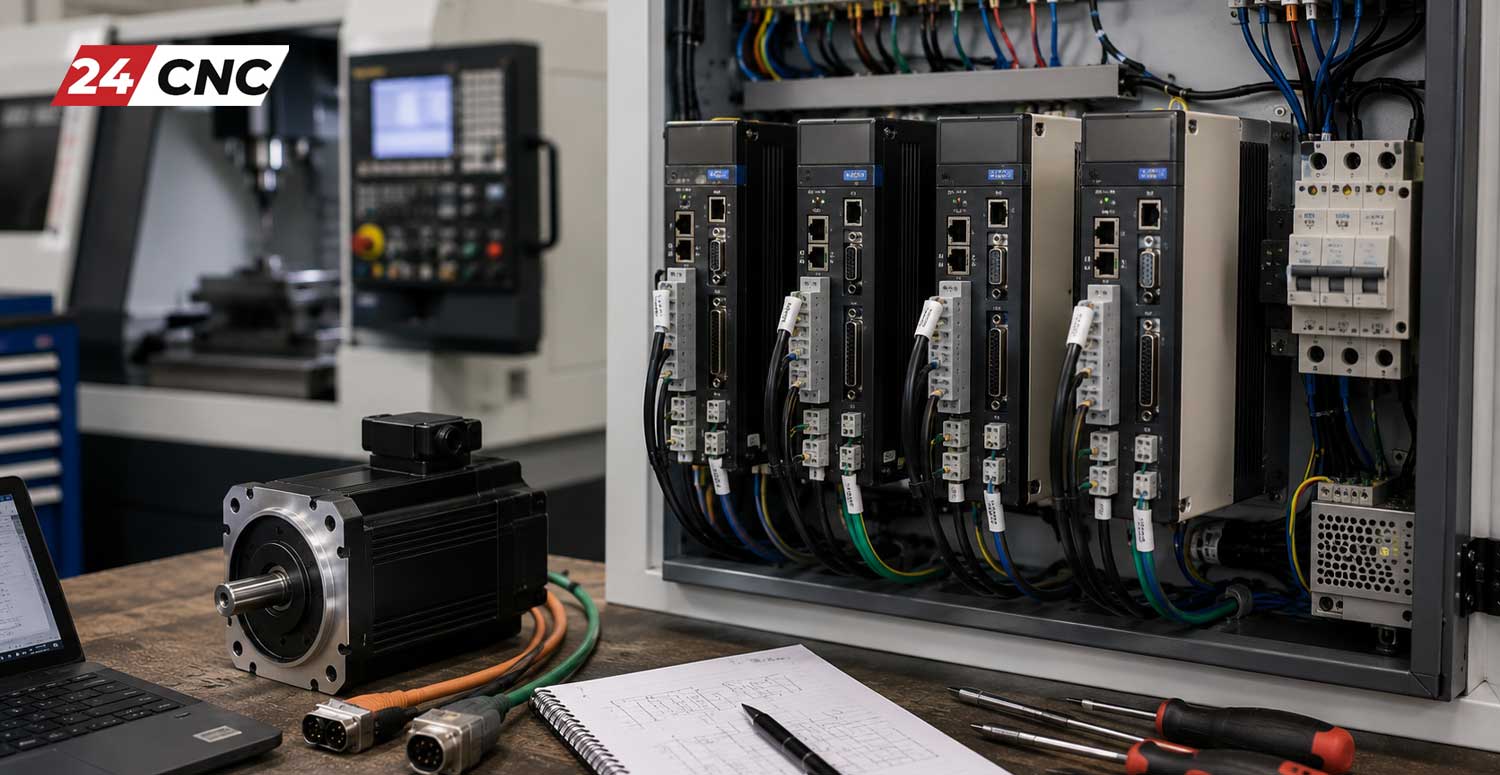
When you watch a CNC machine effortlessly carve through a solid block of titanium with micron-level precision, you are witnessing a marvel of modern electromechanical engineering. At the heart of this precise motion lies a critical component that bridges the gap between the digital brain of the machine and its physical muscle: the CNC servo amplifier, also widely known as a servo drive. Without these sophisticated devices, the rapid, highly controlled movements required for modern machining would be physically impossible.
For machinists, maintenance technicians, and automation enthusiasts entering the CNC industry, understanding how amplifiers and inverters operate is fundamental. This comprehensive guide will demystify the technology behind servo drives, explain their crucial role within the CNC ecosystem, and provide actionable insights into troubleshooting and maintaining these complex industrial components.
What is a CNC Servo Amplifier?
In a typical CNC control system, the main processor calculates the desired path for the cutting tool. It generates low-voltage command signals—often analog voltages ranging from $-10V$ to $+10V$, or digital pulse trains. However, a massive servo motor moving a heavy cast-iron machine table cannot run on a weak $5V$ signal. It requires high voltage and high current.
The servo amplifier acts as the intermediary. It takes the weak command signal from the CNC controller and “amplifies” it, delivering the exact amount of electrical power required to move the motor to the commanded position at the commanded speed. It continuously adjusts the voltage ($V$) and current ($I$) fed to the motor based on mathematical power calculations, where total electrical power is defined as $P = V \times I$.
The Physics of Motion: Closed-Loop Control
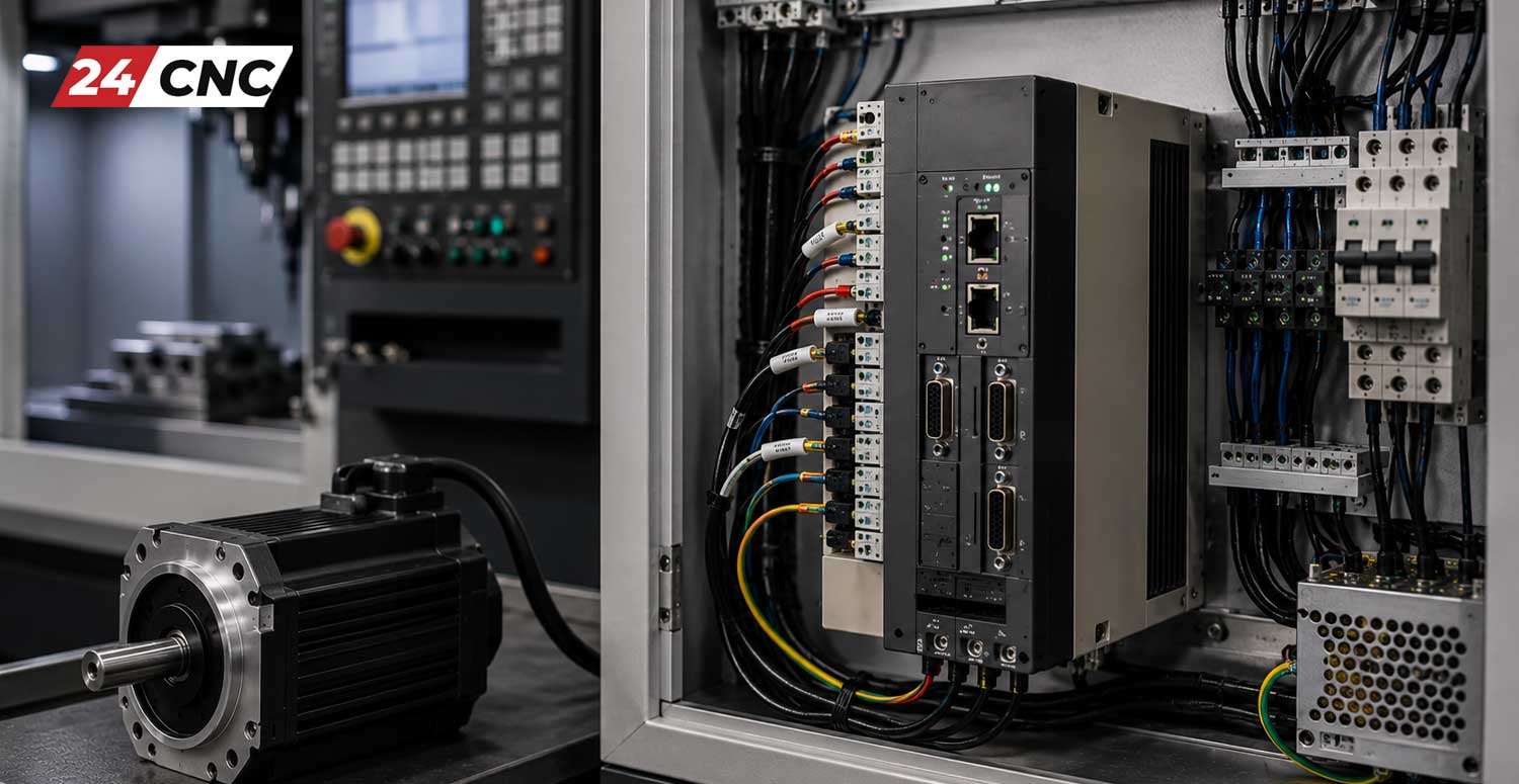
The defining characteristic of a servo system is the “closed-loop” feedback mechanism. Unlike basic stepper motors that operate blindly, a servo system constantly monitors its own performance. The motor is equipped with a rotary encoder that reads the physical position of the motor shaft thousands of times per second.
The drive compares the commanded position from the controller with the actual physical position reported by the encoder. If there is a discrepancy (an error), the drive instantly calculates the necessary torque correction. Torque ($\tau$) is directly proportional to the current applied to the motor, defined by the formula $\tau = K_t \times I$, where $K_t$ is the motor’s specific torque constant. By manipulating the current, the drive forces the error to $0$, ensuring microscopic accuracy.
Core Anatomy of a Servo Drive
A modern industrial servo amplifier is a complex assembly of power electronics and digital microprocessors. To troubleshoot them effectively, one must understand their internal architecture:
- Rectifier Stage: This section takes incoming alternating current (AC) from the factory floor and converts it into direct current (DC). This raw DC power is stored in massive capacitors, creating what is known as the “DC Bus.”
- Inverter Stage (IGBTs): This is the muscle of the drive. The drive utilizes Insulated-Gate Bipolar Transistors (IGBT modules) to rapidly switch the DC bus voltage on and off thousands of times a second. This process, called Pulse Width Modulation (PWM), simulates a precise AC waveform to drive the motor.
- Control Logic Board: This contains the microprocessors that handle the complex PID (Proportional-Integral-Derivative) loop calculations, process the encoder feedback, and communicate with the main CNC controller.
- Feedback Interface: Dedicated circuitry designed to receive the delicate, high-speed signals from the motor’s encoder through specialized, shielded encoder cables.
Technical Comparison: Servo Drives vs. VFDs
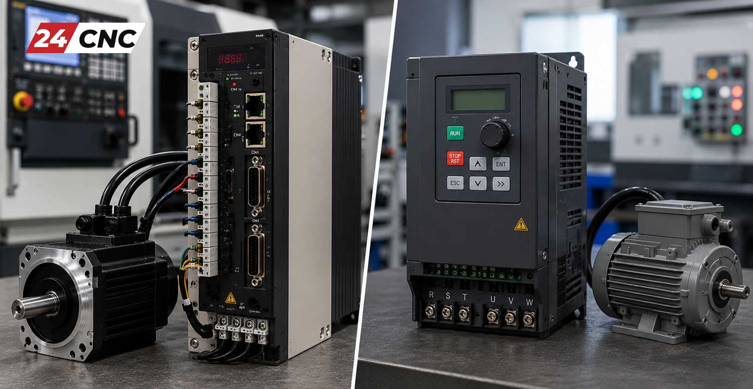
A common point of confusion for beginners is the difference between a Variable Frequency Drive (VFD) and a Servo Drive. While both control electric motors by altering voltage and frequency, their applications and capabilities are vastly different.
| Feature | Servo Drive / Amplifier | Variable Frequency Drive (VFD) |
|---|---|---|
| Primary Purpose | Precise control of position, velocity, and torque. | Speed control of standard AC induction motors. |
| Feedback System | Always closed-loop (requires high-res encoder). | Typically open-loop (can be closed-loop with add-ons). |
| Response Time | Ultra-fast (milliseconds). Ideal for rapid axis interpolation. | Slower response. Suitable for pumps, fans, and basic spindles. |
| Motor Compatibility | Permanent Magnet Synchronous Motors (PMSM). | Standard asynchronous AC induction motors. |
| Cost | Higher initial investment due to complex electronics. | Highly cost-effective for general motion tasks. |
Industry Standard Servo Drive Brands
The CNC landscape is dominated by a few key manufacturers who have perfected the art of motion control over decades. When sourcing replacement parts or upgrading a machine, you will invariably encounter these industry giants:
- Fanuc™: The undisputed king of CNC reliability. Fanuc™ drives (such as the Alpha and Beta series) are renowned for their bulletproof construction and proprietary fiber-optic communication (FSSB) protocols.
- Mitsubishi: A powerhouse in both factory automation and CNC. Mitsubishi drives offer exceptional tuning capabilities and integrate seamlessly with their proprietary Meldas control platforms.
- Siemens: Dominating the European market, Siemens Sinamics drives provide unparalleled integration, energy recovery systems, and advanced safety integrated features.
- Yaskawa: The inventors of the modern mechatronics concept, Yaskawa Sigma drives are legendary for their auto-tuning algorithms and incredibly high bandwidth response.
Troubleshooting Basic Servo Drive Issues
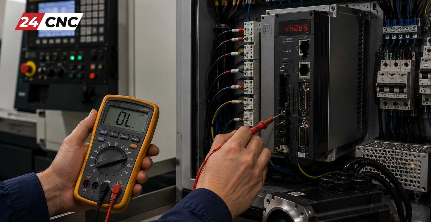
Even the most robust servo amplifiers are subject to harsh industrial conditions. High temperatures, dirty power grids, and mechanical binding on the machine can cause drives to fault out. Here are common issues and diagnostic approaches:
1. Overcurrent Alarms (High Amperage)
An overcurrent alarm occurs when the drive detects that the motor is drawing more current than is safe. This is rarely a fault of the drive itself. Usually, this means the motor is fighting physical resistance. Check the machine for physical crashes, bound up linear guideways, or failed ball bearings. If the mechanics are smooth, inspect the heavy power cables for shorts to ground, which will cause massive current spikes.
2. Overheating / Thermal Faults
Servo drives generate substantial heat from the high-frequency switching of their IGBTs. If a drive throws a thermal alarm, first check the electrical cabinet’s ambient temperature. Next, inspect the internal cooling fans on the drive itself. A dead drive fan will quickly cause the heatsink to saturate, forcing the drive to shut down to prevent melting internal components.
3. Encoder Feedback Errors
If the controller loses track of where the motor is, the machine will instantly halt with a feedback alarm. This is almost exclusively an issue with the encoder cable, the connectors, or the encoder itself. Oil ingress into the motor cap, or a cable that has been repetitively stressed in an energy chain, will disrupt the delicate data packets. Always ensure the shielding on encoder cables is properly grounded to prevent electromagnetic interference (EMI) from corrupting the signal.
Frequently Asked Questions (FAQ)
How long do CNC servo amplifiers typically last?
Under optimal conditions—meaning a clean, climate-controlled electrical cabinet and stable incoming voltage—a high-quality servo drive can easily last 10 to 15 years. The most common wear items are the internal cooling fans and the electrolytic DC bus capacitors, which dry out over time and may require replacement as part of a refurbishment process.
Can I replace a Fanuc drive with a Mitsubishi drive?
Generally, no. Industrial CNC systems are highly proprietary. The communication protocols, encoder feedback formats, and parameter architectures are completely different between brands. You must replace a faulty drive with the exact matching manufacturer and usually the exact same part number to ensure compatibility with your existing control board and motors.
What does “tuning” a servo drive mean?
Tuning involves adjusting mathematical parameters (Proportional, Integral, and Derivative gains) inside the drive’s software. This optimizes how aggressively the motor reacts to commands and corrects errors. A poorly tuned drive will cause the machine axis to vibrate, “sing,” or overshoot its target position, resulting in poor surface finishes on machined parts. Modern drives often include auto-tuning algorithms that calculate these values automatically based on the machine’s physical inertia.
Conclusion
Understanding the fundamentals of CNC servo amplifiers is an essential step for anyone involved in machine maintenance, retrofitting, or automated manufacturing. By grasping the principles of closed-loop feedback, recognizing the distinct hardware components like IGBTs and control boards, and learning the basics of diagnostic troubleshooting, you can significantly reduce machine downtime and keep your production running smoothly.
Need Reliable CNC Servo Amplifiers & Drives?
Whether you are dealing with an overcurrent fault, a blown IGBT module, or simply upgrading your legacy machine, we carry a massive inventory of tested, guaranteed servo drives from top brands like Fanuc, Mitsubishi, and Yaskawa. Minimize your downtime and maximize your precision with premium parts.
Leave a comment
Your email address will not be published. Required fields are marked *