Top 5 CNC Controller Software Options

Top 5 CNC Controller Software Options (Free and Paid)

Every CNC machine, from the massive industrial mills in aerospace factories to the small DIY routers in a garage, requires a brain. That brain is the CNC Controller Software. While the mechanical components—rails, ballscrews, and heavy iron castings—define the machine’s rigidity, it is the software that dictates its precision, capabilities, and ease of use.

Choosing the right control software is arguably the most critical decision in a retrofit project or a new machine build. The wrong choice can lead to lost steps, frustrating crashes, and hours of wasted time. Conversely, the right software seamlessly translates your digital designs into physical reality.

In this comprehensive guide, we will explore the top 5 CNC controller software options available today, ranging from free open-source platforms to professional paid suites. Furthermore, we will discuss how these PC-based solutions compare to dedicated industrial control systems like Fanuc or Siemens, helping you make an informed decision for your workshop.

Understanding the CNC Ecosystem: CAD, CAM, and Control

Understanding the CNC Ecosystem: CAD, CAM, and Control

Before diving into the list, it is vital to clarify where “Controller Software” fits in the manufacturing workflow. Many beginners confuse these three distinct stages:

  1. CAD (Computer-Aided Design): This is where you draw the part (e.g., SolidWorks, Fusion 360).
  2. CAM (Computer-Aided Manufacturing): This software takes your CAD drawing and generates the toolpaths (G-Code).
  3. Control Software: This is the focus of our article. It reads the G-Code file and sends electrical pulses to the servo motors or stepper drivers to move the machine axes.

The control software is the direct interface between the operator and the hardware. It manages the inputs (limit switches, probes) and outputs (spindle on/off, coolant pumps) via a breakout board or motion controller.

1. Mach3 / Mach4 (The Hobbyist & Light Industrial Standard)

For over two decades, ArtSoft’s Mach3 has been the go-to solution for DIY CNC enthusiasts and small job shops. Its successor, Mach4, has since been released to address modern computing requirements.

Mach3

Mach3 essentially turns a standard Windows PC into a CNC controller. Historically, it utilized the parallel printer port (LPT) to send step and direction signals directly to the drivers. While this method is becoming obsolete due to the lack of parallel ports on modern PCs, Mach3 can still be used with USB or Ethernet motion controllers.

  • Pros: Massive community support, thousands of customized screensets, and high compatibility with various MPG handwheels.
  • Cons: Older code base, limited support for modern operating systems (best run on Windows 7 or XP), and the parallel port driver can be unstable on modern CPUs.

Mach4

Mach4 was built from the ground up to be faster and more modular. Unlike Mach3, which was a monolithic program, Mach4 acts more like a “brain” that plugins connect to. It handles high-speed machining much better and integrates seamlessly with modern hardware via adapter cards and Ethernet motion controllers.

LinuxCNC

2. LinuxCNC (The Open-Source Powerhouse)

If you are looking for an industrial-grade solution that costs zero dollars (software-wise), LinuxCNC is the answer. Formerly known as EMC2, this software runs on a Linux operating system equipped with a Real-Time Kernel (RTK).

The “Real-Time” aspect is crucial. Windows is a multi-tasking OS, meaning it might pause the CNC pulse stream to check for an email or run a background update. This causes machine stuttering. LinuxCNC’s RTK ensures the machine takes priority over everything else, providing incredibly smooth pulse generation.

  • Flexibility: It can control up to 9 axes, manage complex kinematics (like hexapods or robot arms), and allows for deep customization of the HAL (Hardware Abstraction Layer).
  • Hardware: It works exceptionally well with older hardware via parallel ports but also supports high-end FPGA main boards (like Mesa cards) for professional retrofits.
  • The Catch: The learning curve is steep. You need to be comfortable with Linux and configuration files.

3. UCCNC (The Modern Competitor)

Developed by CNCDrive, UCCNC has emerged as the strongest competitor to Mach3/4. It is designed to work exclusively with the company’s own motion controllers (like the UC100, UC300, or UC400ETH). By coupling the software tightly with specific hardware, they eliminate many of the communication bugs found in other systems.

The interface is modern, clean, and less cluttered than the default Mach3 screen. It handles high-polygon count 3D surfacing operations very smoothly. For users building a machine who want a “plug and play” experience without the complexity of Linux, UCCNC is often the top recommendation.

4. GRBL (The Minimalist Arduino Solution)

GRBL is high-performance, open-source software that runs on an Arduino microcontroller rather than a PC. The PC simply sends lines of text (G-code) to the Arduino, and the GRBL firmware on the chip handles the pulse generation.

This is the standard for entry-level diode lasers, 3D printers, and small desktop CNC routers. It is free and simple, but it lacks advanced features. You generally won’t find support for tool changers, complex canned cycles, or rigid tapping. Additionally, interfacing with industrial industrial peripherals like high-voltage power supplies or large servo drives can be challenging compared to PC-based controls.

5. PlanetCNC (The Integrated Hybrid)

PlanetCNC takes a unique approach: they sell the software and the hardware controller as a matched pair. The software (TNG) is incredibly feature-rich, offering simulation, advanced g-code manipulation, and a modern USB/Ethernet interface.

Because the hardware and software are developed by the same team, the stability is excellent. It supports features often reserved for high-end controllers, such as warp features (mapping a PCB surface) and extensive SDKs for custom applications.

PC-Based vs. Industrial Dedicated Controllers

PC-Based vs. Industrial Dedicated Controllers (The 24CNC Perspective)

While the software options above are excellent for retrofits and light manufacturing, it is important to distinguish them from dedicated industrial controllers like Fanuc, Siemens, or Mitsubishi.

At 24CNC, we specialize in the components that keep these industrial giants running. Here is the key difference:

  • PC-Based (Mach3, LinuxCNC): The PC does the heavy lifting. If the PC crashes or Windows updates, the machine stops. The wiring involves breakout boards and generic drivers.
  • Dedicated Industrial (Fanuc/Siemens): The “computer” is a hardened, proprietary unit designed to run for 20 years without a reboot. The Fanuc controller communicates with its servo amplifiers via robust fiber optic or high-speed serial protocols, not fragile USB cables.

If you are running a production facility where downtime costs thousands of dollars per hour, you stick with the reliability of Siemens or Fanuc. If you are retrofitting an older bridgeport for a prototype shop, PC-based software is a cost-effective miracle.

For more on this comparison, read our deep dive: Siemens vs. Fanuc vs. Mitsubishi Controller Comparison.

Critical Hardware Considerations for Your Build

Regardless of the software you choose, the software is only as good as the hardware it commands. A LinuxCNC system sending signals to cheap, unshielded wires will result in interference and lost steps. To ensure your software performs correctly, you need to pay attention to:

1. Cabling and Noise Immunity

Electrical noise (EMI) is the enemy of CNC software. Low-voltage signals from your controller to your drives must be protected. Utilizing high-quality, shielded cables is mandatory. Ground loops can cause your software to trigger false “Limit Switch Hit” alarms, halting your job mid-cut.

2. The Human-Machine Interface (HMI)

How you interact with the software matters. Using a mouse and keyboard inside a dusty workshop is clumsy. Professional setups utilize dedicated operator panels. Whether you are looking for a replacement keyboard for a Fanuc system or building a custom panel for Mach4 using arcade buttons and encoders, the tactile feel improves safety and speed.

3. Feedback Systems

Open-loop systems (steppers) blindly follow software commands. Closed-loop systems (servos) report back to the drive or controller. If you are using advanced software like LinuxCNC with a Mesa card, you can close the loop back to the controller using rotary encoders. This allows the software to correct for position errors in real-time.

Technical Comparison: Top 5 Software

Software Cost OS Platform Hardware Requirement Best For
Mach3 $175 Windows (XP-10) Parallel Port or Motion Card Hobbyists, General Retrofits
Mach4 $200 – $1400 Windows Dedicated Motion Controller Advanced Hobby to Industrial
LinuxCNC Free (Open Source) Linux (Real-Time) Parallel Port or FPGA Card Complex Machines, Tech-Savvy Users
UCCNC ~ $60 Windows CNCDrive Hardware (UC Series) Best Value & Stability Balance
GRBL Free Arduino Firmware Arduino Board Lasers, Small Desktop Routers

Choosing the Right Interface Card

Your software choice often dictates your interface hardware. If you choose Mach3 or Mach4, you will need a reliable breakout board to separate the computer’s logic voltage (5V) from the machine’s 24V inputs. For industrial setups involving I/O modules, isolation is key to preventing voltage spikes from frying your PC motherboard.

Furthermore, if you are using an LCD monitor mounted in a control panel, ensure your PC graphics card supports the necessary resolution and that the cabling is routed away from high-power servo lines to prevent screen flickering.

Frequently Asked Questions (FAQ)

Can I use a laptop to run my CNC machine?

Generally, it is discouraged for Mach3 (parallel port) due to power saving features interfering with pulse timing. However, with modern software like UCCNC or Mach4 utilizing Ethernet or USB motion controllers, laptops are perfectly acceptable, provided you disable sleep modes and power-saving settings.

Is LinuxCNC better than Mach4?

“Better” depends on your needs. LinuxCNC is technically superior for complex kinematics and is completely free, but it requires learning the Linux OS. Mach4 is easier to install on a standard Windows PC and has commercial support, which many businesses prefer.

Can I control Fanuc servo motors with Mach3?

Directly? No. Fanuc servos usually use proprietary communication. However, you can retrofit the machine by replacing the drives with ones that accept Step/Dir signals, or by using specialized analog controllers (like CSMIO) that can command older analog servo amplifiers.

What happens if the software crashes mid-cut?

The machine stops receiving pulses, but momentum might carry it forward, breaking the tool. This is why a hardwired E-Stop circuit (independent of software) is mandatory. Also, industrial controllers like Mitsubishi or Siemens rarely crash, which is why they justify their high cost.

Building or Repairing Your CNC Control System?

Software is only half the battle. Whether you need reliable power supplies, replacement I/O modules, or specialized cables to connect your controller to your drives, 24CNC has the industrial-grade parts you need.

Shop CNC Electronics & Parts

How to Read and Understand a CNC Control Panel Wiring Diagram

How to Read and Understand a CNC Control Panel Wiring Diagram

For any CNC technician, maintenance engineer, or retrofitting enthusiast, the electrical cabinet is the heart of the machine. However, opening that cabinet often reveals a daunting maze of colored wires, relays, terminal blocks, and circuit boards. The key to navigating this labyrinth is knowing how to read and understand a CNC control panel wiring diagram. Without this skill, troubleshooting becomes a dangerous guessing game, and retrofitting becomes impossible.

In this comprehensive guide, we will deconstruct CNC electrical schematics, teaching you the language of industrial electronics. Whether you are working with a Fanuc controller, a Siemens system, or a DIY build, the fundamental principles of reading these “maps” remain the same.

The Importance of the "Map": Why You Must Master Schematics

The Importance of the “Map”: Why You Must Master Schematics

A wiring diagram is not just a drawing; it is the logical representation of the machine’s physical reality. It tells you exactly where power enters, how it is transformed, where the logic signals originate, and which device executes the command. Mastering this skill allows you to:

  • Diagnose Faults Quickly: Instead of checking every wire, you can trace the circuit on paper to pinpoint the likely failure point.
  • Safely Replace Components: When swapping out a power supply or a drive, the diagram ensures you connect the new unit correctly, preventing catastrophic damage.
  • Perform Retrofits: Upgrading an old machine requires understanding the existing I/O structure to integrate modern controls.

1. Decoding the Language: Symbols and Standards

The first barrier to understanding a diagram is the symbology. CNC diagrams generally follow one of two major standards: IEC (International Electrotechnical Commission), common in Europe and Asia (Siemens, Fanuc), or NEMA (National Electrical Manufacturers Association), common in North America.

Common Symbols You Will Encounter

While we cannot list every symbol, these are the critical components found in almost every CNC panel:

  • Contacts (NO/NC): The building blocks of logic. “Normally Open” (NO) switches close when activated; “Normally Closed” (NC) open when activated. These are ubiquitous in safety circuits and switches.
  • Coils/Relays: Usually represented by a circle or a rectangle. When energized, they switch the associated contacts.
  • Protection Devices: Look for symbols representing fuses and breakers. In many schematics, a fuse is shown as a rectangle with a line through it or a wavy line.
  • Transformers: Represented by two facing coils, indicating the step-down of voltage (e.g., 220V AC to 24V AC).

2. Following the Power: The High-Voltage Section

When reading a diagram, standard practice is to read from left to right and top to bottom. The logic almost always starts with the incoming power.

Main Disconnect and Distribution

The diagram will start with the 3-phase incoming power (L1, L2, L3). Follow these lines. You will typically see them pass through a main breaker and a noise filter. From there, the power is distributed to:

  1. Servo Drives and Spindle Inverters: These require high voltage. If you are troubleshooting a servo motor issue, trace the high-voltage lines from the drive back to the contactor.
  2. DC Power Supplies: The diagram will show a branch going to a Power Supply Unit (PSU). This unit converts AC to DC (usually 24V) to run the computer and sensors.

Pro Tip: Always verify the power cables on the diagram against the physical labels on the wires. In high-quality CNC machines, wire numbers are printed directly on the insulation.

The Nervous System: Control Logic and I/O

3. The Nervous System: Control Logic and I/O

Once power is established, the diagram shifts to the “brains” of the operation. This is where 24V DC logic reigns supreme. This section of the schematic explains how the controller talks to the machine.

Inputs (The Senses)

Inputs are signals sent to the controller. On the diagram, look for the I/O module section. You will see lines connected to:

  • Limit switches (preventing over-travel).
  • Pressure sensors (hydraulic/pneumatic).
  • Panel buttons (Cycle Start, Feed Hold).

Outputs (The Actions)

Outputs are signals sent from the controller. The diagram will show these wires leading to:

  • Relay coils (to turn on coolant pumps).
  • Solenoid valves (to change tools).
  • Lamps and indicators on the keyboard/panel.

4. Critical Sub-Systems: Feedback and Motion

Perhaps the most complex part of a CNC wiring diagram involves the motion control loops. This is where precision happens.

Encoder Feedback Loops

Servo motors rely on feedback to know their position. On the diagram, look for shielded cables connecting the motor to the drive or the CNC main board. These are often labeled as “Pulse Coder” or “Encoder.”

Because these signals are sensitive to interference, the diagram usually indicates grounding points for the shield. If you are experiencing “drift” or position errors, check the encoder cables on the schematic to ensure the shielding is terminated correctly.

Handwheel (MPG) Wiring

The Manual Pulse Generator (MPG) is the handwheel used for manual jogging. The wiring diagram for the handwheel is specific; it involves 5V power, ground, and two signal phases (A and B). Misinterpreting this section of the diagram is a common cause of “jerky” manual movement.

Understanding Brand-Specific Nuances

5. Understanding Brand-Specific Nuances

Not all diagrams are created equal. A Mitsubishi manual looks very different from a Siemens one. Here is a technical comparison of how major brands structure their electrical documentation.

Feature Fanuc (Japanese Standard) Siemens (European Standard) Mitsubishi (Japanese Standard)
Schematic Logic Often uses “Ladder” logic representation heavily integrated with hardware diagrams. Strict IEC standards. Very structured, page-based referencing (e.g., /12.4). Hybrid approach. Strong focus on “Sink/Source” I/O configuration diagrams.
I/O Naming X (Input) / Y (Output) addresses commonly used. I (Input) / Q (Output) notation (e.g., I0.0, Q4.2). X (Input) / Y (Output) usually in Hexadecimal.
Connector Density High. Uses proprietary Honda connectors frequently. Modular. Uses standardized terminal blocks and PROFIBUS/PROFINET. Compact. Often integrates I/O directly into drives.
Wire Identification Numbering is critical; rarely uses color coding for function. Wire color often dictates voltage (Red=AC, Blue=DC). Similar to Fanuc, heavy reliance on pinout charts.

Practical Troubleshooting Scenarios

Scenario A: The Emergency Stop Loop

The machine won’t start. You open the diagram. Find the “E-Stop” or “Emergency” circuit. It is almost always a series circuit involving the operator panel button, limit switches, and the drive enable signal. By using a multimeter and the diagram, you can test for continuity across each switch in the chain (represented as NC contacts) until you find the open link.

Scenario B: LCD Screen is Dark

If your LCD screen is blank, locate the “Video” or “Display” section of the schematic. Check for two things: the 24V DC power input to the screen and the video signal cable coming from the CNC graphics card. The diagram will give you the pinout to test if voltage is reaching the unit.

Scenario C: Spindle Cooling Fan Failure

Overheating spindle? Find the fan on the diagram. Is it 220V AC or 24V DC? Is it switched by a relay or connected directly to the main bus? The diagram answers this instantly, allowing you to check the fuse or the fan motor itself.

Conclusion: Patience is Key

Reading a CNC control panel wiring diagram is a skill that improves with practice. Start by identifying the major components: the controller, the drives, and the power supply. Trace the lines one by one. Remember, at 24CNC, we specialize in providing the high-quality parts—from connectors to complete control systems—that populate these diagrams. Understanding your machine’s schematic is the first step toward true mastery of CNC maintenance.

Frequently Asked Questions (FAQ)

What is the difference between “Sink” and “Source” wiring in CNC diagrams?

This refers to how current flows in DC circuits. In Source wiring (PNP), the module provides the positive voltage (+) to the load. In Sink wiring (NPN), the module provides the path to ground (-). Getting this wrong in a diagram interpretation can blow your I/O card.

Why are some lines dashed and others solid in the schematic?

Solid lines usually represent physical wires located inside the cabinet. Dashed lines often represent external wiring (field wiring) going to motors or sensors outside the cabinet, or they may indicate a mechanical linkage rather than an electrical connection.

I lost my machine’s wiring diagram. Can I use a generic one?

Generally, no. While the pinouts for standard components like a Siemens controller or a Fanuc amplifier are standard, the specific machine wiring (safety loops, button logic) is unique to the machine builder (OEM). You should try to contact the manufacturer or look for diagrams of identical model numbers.

What do the numbers on the wires mean?

These are “wire numbers” or “potential numbers.” In a professional diagram, every wire that is electrically common (connected together) shares the same number. If a wire passes through a switch or a load, the number changes. This is vital for tracing circuits with a multimeter.

Need Parts to Complete Your Circuit?

Whether you are replacing a faulty encoder, upgrading a servo drive, or sourcing hard-to-find connectors for your Fanuc or Siemens system, 24CNC has the inventory you need. Don’t let a wiring issue stop your production.

Explore CNC Parts Store

CNC Control Panel Functions Explained A Complete Guide to Every Button and Symbol

CNC Control Panel Functions Explained: A Complete Guide to Every Button and Symbol

The heart of any CNC (Computer Numerical Control) machine lies not just in its spindle or servo motors, but in the interface that bridges the gap between human intent and mechanical action: the CNC Control Panel. Whether you are a seasoned machinist or an apprentice just stepping onto the shop floor, mastering the intricate array of buttons, switches, and screens is fundamental to precision manufacturing.

In this comprehensive guide, we will demystify the CNC control panel functions, breaking down the complex cryptic symbols into actionable knowledge. From standard Fanuc interfaces to Siemens and Mitsubishi controllers, we cover the essential inputs that drive modern machining.

The Anatomy of a CNC Controller

The Anatomy of a CNC Controller

While every machine builder (OEM) may customize the layout, the fundamental architecture of a CNC control system remains consistent. The panel is generally divided into two main sections: the Display Unit (MDI/CRT unit) and the Machine Operation Panel.

1. The Display Screen and MDI Unit

The upper portion of the console typically houses the screen and the keypad. This is where the G-code programs are viewed, edited, and managed.

  • The Monitor (CRT/LCD): Older machines use CRT monitors, while modern systems utilize flat-panel LCDs. If your screen is fading or flickering, it may be time to replace the LCD monitor to ensure operators can read coordinates accurately. Brands like Sharp and NEC are common in industrial controllers.
  • Soft Keys: These are the row of blank buttons located directly under the screen. Their function changes based on what is currently displayed on the menu (e.g., OFFSET, SETTING, PROGRAM).
  • Data Input Keypad: Similar to a standard computer keyboard but optimized for code entry. This area often suffers from wear and tear due to oil and coolant exposure. High-quality replacement keyboards and membranes are essential for maintaining input accuracy.

2. The Machine Operation Panel

Located typically below the screen, this section contains the physical switches, dials, and buttons used to physically move the machine axes and start programs. This area relies heavily on robust switches and rotary selectors.

Mastering the Mode Selector Switch

The most critical dial on the panel is the Mode Selector. This rotary switch determines the machine’s state of operation. Understanding these modes is the first step in learning CNC control panel functions.

EDIT Mode

Used for entering, altering, or deleting part programs stored in the machine’s memory. In this mode, the machine will not execute movement, making it safe for coding changes.

MEM / AUTO (Memory/Automatic)

This is the production mode. The machine executes the active program stored in the memory. Once you press “Cycle Start,” the machine follows the G-code instructions autonomously.

MDI (Manual Data Input)

MDI allows you to execute short, one-time commands without creating a full program. For example, if you need to perform a tool change (e.g., T01 M06) or spin the spindle (S1000 M03) for a quick test, you use MDI mode.

JOG Mode

JOG mode allows the operator to move the axes (X, Y, Z) continuously using the axis direction buttons (+X, -X, etc.). The speed of this movement is usually determined by the Feed Rate Override switch.

HND / MPG (Handle Mode)

For precision setup, nothing beats the Manual Pulse Generator (MPG). This mode activates the handwheel, allowing the operator to move axes in increments as small as 0.001mm or 0.0001 inches. If your dial is skipping steps, you may need to inspect the handwheel (MPG) or check the handwheel cable for continuity issues.

ZRN / REF (Zero Return)

This mode sends the machine axes to their home position (Machine Zero). This is a mandatory step upon starting up most CNC machines to calibrate the rotary encoders and establish the coordinate system.

Critical Operation Buttons and Switches

Beyond the modes, specific buttons control the immediate behavior of the machine tool.

Cycle Start and Feed Hold

  • Cycle Start: Usually a green button. It initiates the program execution in MEM or MDI mode.
  • Feed Hold: Usually a red button. It pauses axis motion immediately but keeps the spindle running. It is a “pause” button for the machining process.

Overrides (Feed and Spindle)

Machinists rarely run a program at 100% speed on the first run. Override switches allow real-time adjustment.

  • Feed Rate Override: A selector switch that adjusts the cutting feed from 0% to roughly 150% or 200%.
  • Spindle Speed Override: Adjusts the RPM of the spindle motor. If you notice the spindle speed fluctuating irrespective of the override, checking the servo motor or the amplifier/inverter might be necessary.

Emergency Stop (E-Stop)

The large, mushroom-shaped red button. Pressing this cuts power to the servo drives and spindle immediately. It is a hardware-wired safety feature. If an E-Stop alarm persists even when the button is released, the contact block or the power supply unit feeding the safety circuit may be faulty.

Single Block & Optional Stop

  • Single Block (SBK): When active, the machine executes one line of G-code and then stops. The operator must press Cycle Start to run the next line. Crucial for proving out new programs.
  • Optional Stop (M01): If this switch is On, the machine will stop whenever it reads an M01 code in the program.

Controller Variations: Fanuc vs. Siemens vs. Mitsubishi

Controller Variations: Fanuc vs. Siemens vs. Mitsubishi

While the functions are similar, the hardware execution differs. Choosing the right replacement parts requires identifying your specific system.

Feature/Aspect Fanuc Controller Siemens Controller Mitsubishi Controller
Interface Style Classic, code-heavy, uses “Soft Keys” extensively. Conversational (ShopMill/ShopTurn), graphical buttons. Hybrid, known for high-speed processing menus.
Key Components Requires specific Fanuc modules and yellow-capped motors. Uses distinct Siemens control parts and PLCs. Integrates well with Mitsubishi drives.
Program Transfer PCMCIA Card / CF Card via adapter. USB / Network usually built-in on front. CF Card / Ethernet.

Common Panel Hardware Issues and Fixes

Common Panel Hardware Issues and Fixes

A malfunctioning panel can halt production. Here are common hardware failures related to control panel functions:

  1. Unresponsive Buttons: Often caused by oil ingress behind the membrane. Cleaning or replacing the keyboard membrane usually fixes this.
  2. Black Screen: If the machine runs but the screen is dark, the backlight inverter or the LCD panel itself has likely failed.
  3. Erratic Axis Movement: If turning the MPG causes the axis to jump or not move smoothly, check the optical cables or the internal encoder of the handwheel.
  4. System Errors on Boot: Errors related to “Parity” or “System Watchdog” can indicate issues with the main board or memory modules.

Frequently Asked Questions (FAQ)

Q: What is the difference between MDI and AUTO mode?

A: AUTO mode runs a full program saved in the memory continuously. MDI (Manual Data Input) is used for entering and executing single lines of code manually for setup or maintenance tasks.

Q: Why is my Cycle Start button not working?

A: This could be due to an active Feed Hold, an open door interlock (safety sensor), or a physical failure of the switch mechanism. Check if the button light is active or if there are alarms on the screen.

Q: Can I replace a CRT monitor with an LCD?

A: Yes. Converting old CRT monitors to modern LCD screens is a very common upgrade that improves visibility and reduces energy consumption and heat.

Q: What does the “Dry Run” button do?

A: Dry Run allows the machine to execute the program at a high feed rate defined by the parameter settings, ignoring the programmed feed rates. It is used to quickly check tool path movements without cutting metal (usually with no part in the vice).

Need Replacement Parts for Your CNC Panel?

From Fanuc membranes and Siemens displays to handwheels and critical control boards, keep your downtime to a minimum with high-quality spares.

Browse Control System Parts

The Ultimate Guide to Building a DIY CNC Controller from Scratch

The Ultimate Guide to Building a DIY CNC Controller from Scratch

For hobbyists, engineers, and machinists alike, the heart of any CNC machine is its controller. While the mechanical frame provides the structure, the controller provides the intelligence. Building a DIY CNC controller from scratch is not only a cost-effective way to power your machine, but it also gives you an intimate understanding of how your system operates, making future maintenance and upgrades significantly easier.

In this comprehensive guide, we will walk you through the entire process: selecting the right components, understanding wiring schematics, managing power distribution, and configuring the software. Whether you are retrofitting an old mill or building a router from the ground up, this guide is your blueprint for motion control success.

The Anatomy of a CNC Controller

1. The Anatomy of a CNC Controller

Before heating up the soldering iron, it is crucial to understand what actually goes inside the control box. A robust controller is a symphony of electronic components working in unison. At its core, the system translates digital G-code instructions from your computer into physical electrical pulses that move motors.

The primary subsystems you will need to assemble include:

  • The Brain (Interface Board/Motion Controller): Interprets signals from the PC.
  • The Muscle (Motor Drivers): Amplifies low-voltage signals to drive stepper or servo motors.
  • The Heart (Power Supply Unit): Provides the necessary DC voltage to the drivers and boards.
  • The Nervous System (Wiring & Connectors): Transmits signals and power safely.

2. Selecting the Critical Hardware

The quality of your build depends entirely on the components you choose. Let’s break down the essential parts list.

The Motion Controller / Breakout Board

This is the bridge between your computer and the machine. For DIY builds, you generally have three routes:

  • Arduino/Microcontroller based (GRBL): Excellent for simple 3-axis routers and laser cutters.
  • Parallel Port Breakout Boards (Mach3/LinuxCNC): The classic choice for retrofits, though requiring a PC with a parallel port or a smooth stepper adapter.
  • Dedicated All-in-One Controllers: Industrial-grade options like dedicated control systems offer higher reliability but at a higher cost.

Stepper Motor Drivers

Your microcontroller cannot drive motors directly. You need drivers. Common DIY choices include the TB6600 (entry-level) or the DM542/DM556 (digital, quieter, and smoother). If you are aiming for high precision, consider closed-loop stepper drivers or even servo motors for position feedback and error correction.

Power Supply Unit (PSU)

Selecting the right power supply is critical. You need to match the voltage to your stepper drivers’ capabilities (usually 24V, 36V, or 48V). A higher voltage generally allows for higher motor speeds. Ensure your PSU has enough amperage to cover all motors running simultaneously plus a 20% safety margin.

Enclosures, Cooling, and Layout

3. Enclosures, Cooling, and Layout

A pile of wires on a workbench is a hazard. You need a proper enclosure. When laying out your components inside a metal cabinet (which helps with EMI shielding), consider the heat.

Stepper drivers and power supplies generate significant heat. You must incorporate active cooling. Installing high-quality cooling fans is mandatory to prevent thermal shutdown during long machining jobs. Plan your airflow so that cool air is pulled in from the bottom and hot air is exhausted out the top.

4. The Art of Wiring: Connectivity and Safety

Wiring is where most DIY builds succeed or fail. “Noise” or Electromagnetic Interference (EMI) can cause your machine to behave unpredictably—stopping mid-job or missing steps.

Shielding and Grounding

Always use shielded cables for your stepper motors and limit switches. The shield (the metal mesh inside the cable) acts as a cage, trapping interference. Crucial tip: Only ground the shield at the controller end (star ground), never at the motor end, to prevent ground loops.

Connectors and Sockets

Do not just twist wires together. Use proper sockets and connectors. Aviation plugs (GX16) are a standard in the DIY CNC community because they screw lock, ensuring vibrations don’t shake a connection loose.

Fuses and E-Stops

Safety is not optional. Your mains power input should be fused. Additionally, individual fuses for your drivers can save expensive components if a motor shorts out. Check out various fuse series to find the right amperage for your setup. Finally, install a physical Emergency Stop (E-Stop) button that cuts power to the drives immediately.

5. Adding Advanced Peripherals

Once the axes are moving, you can upgrade your controller’s functionality.

Limit and Homing Switches

These sensors tell the controller where the physical limits of the machine are. Inductive proximity sensors are often preferred over mechanical switches because they don’t wear out and are less susceptible to dust.

MPG Handwheels

Trying to position a CNC machine by tapping keyboard keys is frustrating. Integrating an MPG Handwheel allows you to manually jog the machine with professional precision, making setting up work zeros significantly faster.

Software Configuration

6. Software Configuration

With hardware assembled, you must configure your software (Mach3, Mach4, UCCNC, or GRBL). You will need to calculate your “Steps Per Unit.” This formula depends on your motor step angle (usually 1.8 degrees), your driver micro-stepping setting, and the pitch of your leadscrew or ball screw.

Formula: (Steps per Revolution x Microsteps) / Pitch of Screw = Steps Per Unit.

7. Troubleshooting Common DIY Controller Issues

Ghosting/Random Movements: usually caused by EMI. Check your grounding and ensure high-voltage cables (spindle power) are not running parallel to low-voltage signal cables.

Overheating Drivers: Check your current (amperage) dip switch settings on the driver. If they are set too high for the motor, the motor will overheat. If the driver overheats, check your drive cooling fans.

Comparison: Control Ecosystems

Feature Arduino (GRBL) Mach3/Mach4 (PC Based) Industrial (Fanuc/Siemens)
Cost Very Low Moderate High
Complexity Beginner Friendly Intermediate Professional
Real-time Performance Limited (8-bit) Good (Depends on PC) Excellent (Dedicated Hardware)
Best Application 3D Printers, Lasers, Small Routers Retrofits, DIY Mills Production Machines
Peripherals Limited Extensive (MPG, Probes) Fully Integrated

8. Conclusion

Building a DIY CNC controller is a rewarding project that bridges the gap between electronics and mechanics. By carefully selecting your power supply, drivers, and implementing proper wiring hygiene with shielded cables and quality connectors, you can build a system that rivals commercial units.

Remember, a CNC machine is only as reliable as its weakest link. Don’t skimp on the essentials like cooling, grounding, and power protection. Take your time, double-check your schematics, and enjoy the precision that comes from a machine you built with your own hands.

Frequently Asked Questions

Q: Can I use a computer power supply (ATX) for my CNC?

A: While possible for very small Arduino setups, it is not recommended for larger machines. ATX supplies often lack the voltage (usually only 12V) required for high-speed stepper motor operation. Dedicated CNC power supplies (24V, 36V, 48V) are far superior for torque and speed.

Q: Why do my motors lose steps?

A: Lost steps are usually caused by mechanical binding, aggressive acceleration settings in software, or electromagnetic interference (EMI). Ensure you are using shielded cables properly grounded to the controller side.

Q: What is the difference between a breakout board and a motion controller?

A: A breakout board simply gives you screw terminals to access the pins of a PC’s port (like Parallel). A motion controller (like a USB or Ethernet board) has its own processor to generate the pulses, taking the load off the computer and providing smoother motion.

Q: Do I need a specific fan for the controller box?

A: Yes. Stepper drivers generate heat. If they get too hot, they will cut out to protect themselves. Always install fans to ensure positive airflow through the enclosure.

Ready to Build Your Dream Machine?

Whether you are looking for specific capacitors, industrial-grade Fanuc controllers, or high-quality cables to finish your DIY build, 24CNC has the parts you need.

Explore CNC Parts Store

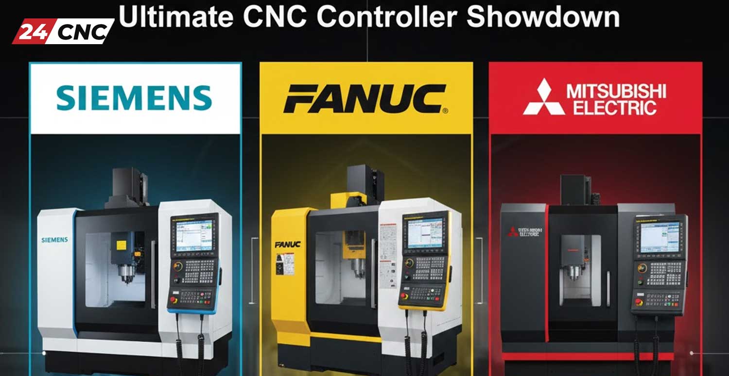
Siemens vs. Fanuc vs. Mitsubishi The Ultimate CNC Controller Showdown

Siemens vs. Fanuc vs. Mitsubishi: The Ultimate CNC Controller Showdown

The “brain” of any modern machine shop is the CNC controller. It dictates not just how a machine moves, but how your operators interact with it, how fast you can go from print to part, and how much downtime you might face over the next decade. Choosing between the “Big Three”—Siemens, Fanuc, and Mitsubishi—is rarely a simple decision. It is a strategic choice that impacts your workflow, your maintenance budget, and your bottom line.

At 24cnc.com, we supply parts for all major systems, so we have a unique, unbiased view of what breaks, what lasts, and what users actually prefer. In this comprehensive guide, we will break down the strengths, weaknesses, and ideal use cases for the three giants of the CNC world.

The Global Heavyweight: Fanuc

The Global Heavyweight: Fanuc

Fanuc (Fuji Automatic NUmerical Control) is undeniably the market leader, holding a massive share of the global CNC market. If you walk into almost any job shop in the world, you are likely to see a machine with that iconic yellow styling.

The “Fanuc Standard” of Reliability

The primary selling point of a Fanuc Controller is its legendary reliability. These systems are often described as “bulletproof.” It is not improved uncommon to see 30-year-old Fanuc controls still running daily production. This reliability extends to their hardware ecosystem, including their robust Fanuc servo motors and drives.

Pros of Fanuc:

  • Ubiquity: Because they are so common, finding operators who know G-code for Fanuc is easy.
  • Backward Compatibility: Programs written for a Fanuc system from the 90s will often run on a modern Series 30i model with minimal changes.
  • Parts Availability: Whether you need a Fanuc power supply or a replacement input/output module, parts are readily available, keeping downtime to a minimum.

Cons of Fanuc:

  • User Interface: Older models, and even some newer ones, are criticized for having a dated, menu-heavy interface compared to modern touchscreen expectations.
  • Cost of Options: Fanuc is notorious for charging extra for software features that might be standard on other controls.

The Technological Powerhouse: Siemens

The Technological Powerhouse: Siemens

While Fanuc dominates in standard reliability, Siemens is often viewed as the leader in high-end technological capability and user experience. The Siemens Sinumerik series is a favorite in the aerospace and automotive industries where complex 5-axis machining is common.

ShopMill and ShopTurn: A Programmer’s Dream

Siemens shines with its conversational programming. Their “ShopMill” and “ShopTurn” interfaces allow operators to program complex parts directly at the machine using visual prompts, without needing to know a single line of G-code. This can drastically reduce setup time for high-mix, low-volume shops.

Pros of Siemens:

  • Advanced Interface: Modern Siemens controls feature large, high-resolution screens (often requiring specific Siemens keyboards and labels) that feel like using a smartphone or tablet.
  • Digital Twin Technology: Siemens is a pioneer in digitalizing manufacturing, allowing for superior simulation and integration with CAD/CAM systems.
  • 5-Axis Superiority: For complex mold and die work, Siemens’ motion control algorithms are often considered the gold standard.

Cons of Siemens:

  • Learning Curve: For operators raised on Fanuc G-code, the Siemens structure can feel foreign initially.
  • Complexity: The sheer number of parameters can be overwhelming for simple 2-axis lathe work.

The Cost-Effective Performer: Mitsubishi

The Cost-Effective Performer: Mitsubishi

Mitsubishi Electric sits comfortably as a strong competitor that balances high performance with cost-effectiveness. The Mitsubishi control systems, particularly the M8 series, are incredibly fast and are standard on many high-speed tapping centers (like Brother or Mazak machines, which often use modified Mitsubishi controls).

Speed and Integration

Mitsubishi controls are known for their high-speed processing capabilities. They integrate seamlessly with Mitsubishi drives and motors to provide rapid acceleration and deceleration, which is critical for reducing cycle times in mass production environments.

Pros of Mitsubishi:

  • Value: Generally offers a higher performance-to-price ratio than Fanuc or Siemens.
  • User-Friendly: Newer models offer a dual-mode interface—standard G-code for veterans and conversational programming for newer machinists.
  • Robust Hardware: Like Fanuc, Mitsubishi hardware is durable. However, should you need repairs, finding a Mitsubishi encoder or amplifier is straightforward.

Cons of Mitsubishi:

  • Market Share: While popular in Asia, they have less market penetration in the US and Europe compared to Fanuc, meaning fewer trained specialized technicians may be available locally.

Hardware and Maintenance Comparisons

Regardless of which controller you choose, eventually, hardware wears out. Understanding the maintenance ecosystem is vital.

Screens and Interfaces

The HMI (Human Machine Interface) is the most touched part of the machine. Over time, LCDs dim or crack. Fanuc often uses robust screens, but upgrading or replacing them is common. Siemens tends to use larger, more proprietary displays. At 24cnc, we stock replacement LCD panels for all three brands, including specialized options like Sharp LCDs often found in older control units.

Drives and Motors

The “muscle” of the machine involves the servo amplifiers and spindle drives.

Fanuc: Their drives are modular but can be sensitive to power fluctuations. Ensuring you have good fuses and cooling is key.

Mitsubishi: Their drives are compact and highly efficient.

Siemens: Often uses a bus system that is very tidy but requires careful matching of components.

Check our Amplifier and Inverter section for replacements across all brands.

Sensors and Feedback

Accuracy depends on feedback. Whether it’s a Fanuc Pulse Coder or a specialized sensor, these components are the first line of defense against bad parts. Fanuc’s serial feedback system is proprietary, whereas Siemens and Mitsubishi can sometimes be more flexible with third-party scales, though sticking to OEM is always recommended.

Technical Comparison at a Glance

Feature Fanuc (Series 0i/30i) Siemens (Sinumerik 828D/840D) Mitsubishi (M8 Series)
Primary Strength Reliability & Market Share Advanced Tech & 5-Axis High Speed & Cost Value
Programming G-Code Focused (Manual Guide i) Conversational (ShopMill/Turn) Hybrid (G-Code + Conversational)
Spare Parts Access Excellent (Global availability) Good (Strong in Europe) Good (Growing in West)
Learning Curve Moderate (Industry Standard) Low for beginners, High for experts Moderate
Key Components Fanuc Controllers Siemens Controllers Mitsubishi Drives

Common Accessories and Retrofitting

No matter which controller you run, the peripherals are often universal or require specific adapters.

  • Handwheels (MPG): Operators love a good manual pulse generator. Whether you need a standard MPG or a specific MPG60, these are essential for setup.
  • Cooling: Electronics hate heat. Keeping your cabinet cool with the right fan is the cheapest insurance policy you can buy.
  • Cabling: Communication errors are often just bad cables. High-quality optical cables are crucial for modern, high-speed data transfer in newer controls.

Frequently Asked Questions (FAQ)

Which CNC controller is easiest to learn?

For absolute beginners with no G-code experience, Siemens (with ShopMill/ShopTurn) is generally considered the easiest because it uses graphical, conversational programming. However, because Fanuc is so common, more training resources and experienced mentors are available for it.

Are Fanuc parts interchangeable with Mitsubishi?

Generally, no. The communication protocols, voltage requirements, and connectors are different. You cannot plug a Mitsubishi motor into a Fanuc drive. However, some general accessories like switches or cooling fans may be generic.

Which controller is best for high-speed machining?

While all three have high-speed options, Mitsubishi is famous for its high-speed processing in tapping centers, and Siemens 840D is renowned for high-speed 5-axis contouring smoothness.

Where can I buy replacement keys or membranes?

Keypads wear out frequently. We stock a wide variety of labels and keyboards for Fanuc, Siemens, and other controllers to get your operator panel looking and working like new.

Final Verdict: Which One Should You Choose?

The “best” controller depends entirely on your shop’s needs:

  1. Choose Fanuc if: You want maximum reliability, you are in a production environment where downtime is not an option, and you want access to the largest pool of qualified operators and spare parts.
  2. Choose Siemens if: You are doing high-mix/low-volume work, complex 5-axis machining, or want a modern, graphical user interface that helps new operators produce parts faster.
  3. Choose Mitsubishi if: You need high-speed performance for mass production (like drilling/tapping) and want a cost-effective solution without sacrificing durability.

Regardless of the logo on the front of the cabinet, keeping your machine running requires a reliable partner for parts. From control cards to sensors, maintaining your CNC investment is what we do best.

Need Parts for Your CNC Controller?

Whether you run Fanuc, Siemens, or Mitsubishi, downtime costs money. Browse our extensive inventory of high-quality replacement parts, from servo motors to main boards.

Explore CNC Control Parts Now

What is a CNC Controller and How Does It Work? The Ultimate 2026 Guide

What is a CNC Controller and How Does It Work? The Ultimate 2026 Guide

In the precise world of automated manufacturing, the CNC Controller is the undisputed brain of the operation. Whether you are running a high-speed production line or maintaining a custom workshop, understanding the intricacies of your control system is vital. From the simplest DIY router to complex 5-axis industrial mills, the controller dictates every move, every cut, and every safety protocol.

This ultimate 2026 guide will break down the anatomy of a CNC system, explaining how digital code transforms into physical motion. We will also explore the critical hardware ecosystem—from control systems and servo motors to the essential cables that connect them.


Defining the CNC Controller

Defining the CNC Controller

At its core, a CNC (Computer Numerical Control) Controller is a specialized computer designed to control machine tools. It reads a program (usually G-code) and converts those instructions into synchronized electrical pulses. These pulses drive the axes of the machine to specific coordinates with micron-level accuracy.

However, a modern controller is more than just a pulse generator. In 2026, advanced control systems manage the entire machining environment. They monitor spindle load, manage tool changers via I/O modules, and ensure operator safety through rigorous feedback loops.

The Anatomy of a CNC System: Key Components

To fully grasp how a controller works, you must look at the hardware ecosystem it commands. A controller does not act alone; it relies on a network of specialized parts.

1. The Human-Machine Interface (HMI)

This is the point of contact between the operator and the machine. It typically consists of an LCD Screen (often manufactured by brands like Sharp, NEC, or Toshiba) which displays coordinates and simulation graphics. Below the screen, you will find the keyboard and control panel labels. Over time, the tactile switches on these panels wear out, making replacement Fanuc keyboards or generic membranes a common maintenance item.

2. Motion Control & Drives

The controller calculates the path, but the Amplifier and Inverter (often called the servo drive) provides the muscle. The controller sends low-voltage signals to the drive, which then amplifies this into high-power current to turn the servo motor.

For specific systems, matching the drive to the motor is crucial. For example, a Fanuc drive is engineered to communicate perfectly with a Fanuc motor.

3. Feedback Systems (Encoders)

Accuracy is achieved through feedback. Rotary Encoders are attached to the motors to track the exact shaft position.

  • Incremental encoders report relative movement.
  • Absolute encoders (common in Mitsubishi and Fanuc systems) know exactly where they are even after a power loss.

4. Manual Control Devices

For setup and calibration, operators use a Handwheel (MPG). Whether it is a wired MPG or a modern wireless handwheel, these devices allow for manual “jogging” of the axes using a selector switch.

How It Works: The Data to Motion Workflow

How It Works: The Data to Motion Workflow

The magic of CNC happens in milliseconds. Here is the step-by-step workflow of a working cycle:

  1. Input: The operator loads a program via a CF Card or network connection.
  2. Processing: The Main Board of the controller parses the G-code. It looks ahead to calculate acceleration and deceleration curves.
  3. Logic Handling: The internal PLC checks the status of all sensors and safety interlocks. If a sensor detects a door open, motion is inhibited.
  4. Signal Transmission: Coordinates are sent to the drives via high-speed optical cables or standard encoder cables to minimize noise interference.
  5. Execution: The motors move the machine table. The encoders send position data back to the controller to verify the move was completed successfully.

Industrial Giants: Fanuc vs. Siemens vs. Mitsubishi

Not all controllers are created equal. The market is dominated by a few key players, each with their own ecosystem of parts.

Fanuc

Known for legendary reliability, the yellow Fanuc Controller is the industry standard. Their ecosystem is vast, including proprietary power supplies and distinct I/O modules. They are the workhorses of the automotive and aerospace industries.

Siemens

The Siemens Controller (Sinumerik series) is renowned for its high-end processing power and flexibility. It is often favored in complex 5-axis machining throughout Europe.

Mitsubishi & Others

Mitsubishi controls are famous for high-speed processing in mold making. Other brands like Delta and Yaskawa provide excellent servo systems that integrate with various generic controllers.

Maintenance & Hardware Replacement

Even the best systems fail. Heat, vibration, and time take their toll on electronics. Keeping a CNC machine running often involves troubleshooting specific sub-components.

  • Cooling: Overheating is a major killer of electronics. Regularly checking the cooling fans inside the cabinet and on the spindle motor is essential.
  • Power Integrity: Spikes in voltage can damage sensitive boards. A stable power supply is critical. Always check fuses first when a system won’t power up.
  • Connectivity: Old cables become brittle. Faulty cables are a common cause of erratic jogging behavior. Similarly, ensuring tight connections with high-quality sockets and connectors prevents intermittent signal loss.
  • Board Repair: Sometimes the issue lies deep within the circuitry. Failing IC Hybrids or IGBT modules in the drive can cause motor alarms.

Technical Comparison: Controller Ecosystems

Technical Comparison: Controller Ecosystems

Choosing a control system dictates the hardware you will use for the life of the machine. Here is how the major ecosystems compare.

Feature / Brand Fanuc Ecosystem Siemens Ecosystem Mitsubishi Ecosystem
Primary Communication FSSB (Optical Fiber) Drive-CLiQ SSCNET III/H (Optical)
Feedback Device Fanuc Absolute Encoder Heidenhain / Siemens Mitsu High-Res Encoder
HMI Display Dedicated LCD Unit PC-based or Panel Touchscreen Integration
Drive Technology Alpha / Beta Series Drives Sinamics Modules Meldas / M80 Series

Frequently Asked Questions (FAQ)

Why is my CNC controller screen blank?

A blank screen can be caused by a failed backlight on the LCD panel, a loose video cable, or a power supply issue. Check the fuses on the power unit first. If the screen is old, the inverter powering the backlight may need replacement.

Can I replace a Fanuc Encoder with a generic one?

Generally, no. Fanuc encoders use a proprietary communication protocol to talk to the servo amplifier. Using a generic encoder will usually result in a communication alarm. Always replace with the exact part number.

What is the function of the I/O Module?

The I/O (Input/Output) module acts as the nervous system for auxiliary functions. It takes signals from switches, buttons, and sensors, and sends commands to relays (like turning on coolant or opening a valve).

My Handwheel (MPG) is skipping steps. What is wrong?

This is a common issue. It is often due to a worn-out optical disk inside the MPG unit, or a damaged handwheel cable that has an intermittent break. Inspect the cable for kinks and consider replacing the MPG unit if it’s old.

Need Replacement Parts for Your CNC Controller?

From rare Fanuc servo amplifiers to the latest wireless handwheels and industrial LCD screens, we stock the hard-to-find components that keep your shop running. Minimize downtime with high-quality spares.

Search for products

Back to Top
Product has been added to your cart