
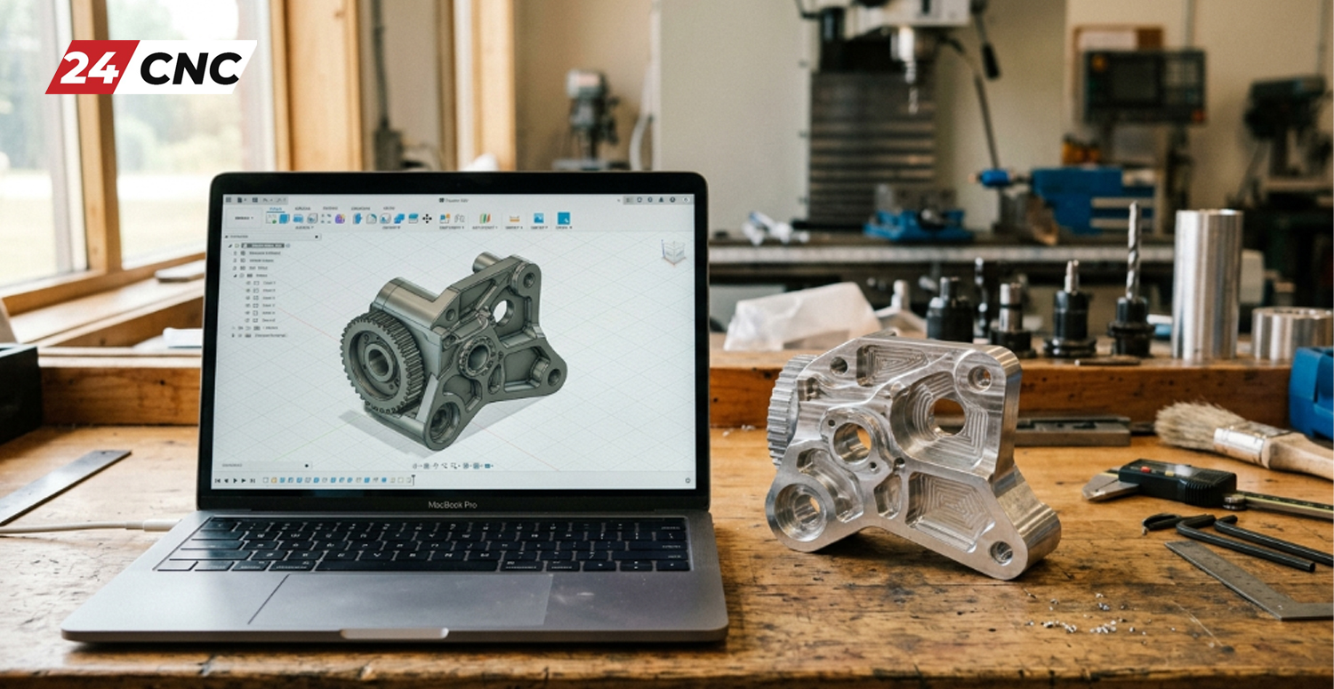
Look at the precision components inside an aerospace engine, the sleek aluminum chassis of a high-end laptop, or the custom titanium implants used in medical surgeries. These items all share a common origin: they were brought into existence through the meticulous and highly controlled process of CNC machining. But exactly how are CNC parts made? To the uninitiated, placing a block of raw metal into a closed machine and watching a perfect, mirror-finish part emerge feels a bit like magic.
The reality, however, is a fascinating intersection of digital design, advanced mathematics, materials science, and heavy mechanical engineering. In this comprehensive pillar guide, we will pull back the curtain on the manufacturing floor. We will trace the lifecycle of a CNC part step-by-step—from the initial spark of an idea inside a 3D modeling software environment all the way to the final physical product. If you are new to this field, you may also want to start by reviewing what is CNC machining broadly before diving into this detailed workflow.
Step 1: The Blueprint – 3D CAD Modeling
Every physical part begins its life in the digital realm. The manufacturing process cannot start until there is a mathematically perfect representation of the final product. This is achieved using Computer-Aided Design (CAD) software, such as SolidWorks, Autodesk Fusion 360, or Siemens NX.
During the CAD phase, design engineers define the geometry of the part. They dictate the length, width, depth, and complex organic curves. More importantly, this stage defines the tolerances. In machining, a tolerance is the acceptable limit of variation in a physical dimension. For instance, a bearing shaft might require a diameter of exactly $20.00 \text{ mm}$ with a tolerance of $\pm 0.01 \text{ mm}$. The CAD model holds all this critical data.
However, designing for CNC is not the same as designing a purely visual 3D asset for a video game or an animation. Engineers must understand Design for Manufacturability (DFM). They have to consider whether a spinning cutting tool can actually reach the internal corners of their design. Since drill bits are round, creating perfectly sharp internal square corners is physically impossible without specialized processes like EDM. For a deeper understanding of these design constraints, read our guide on how to design parts for CNC machining.
Step 2: The Strategy – CAM Programming
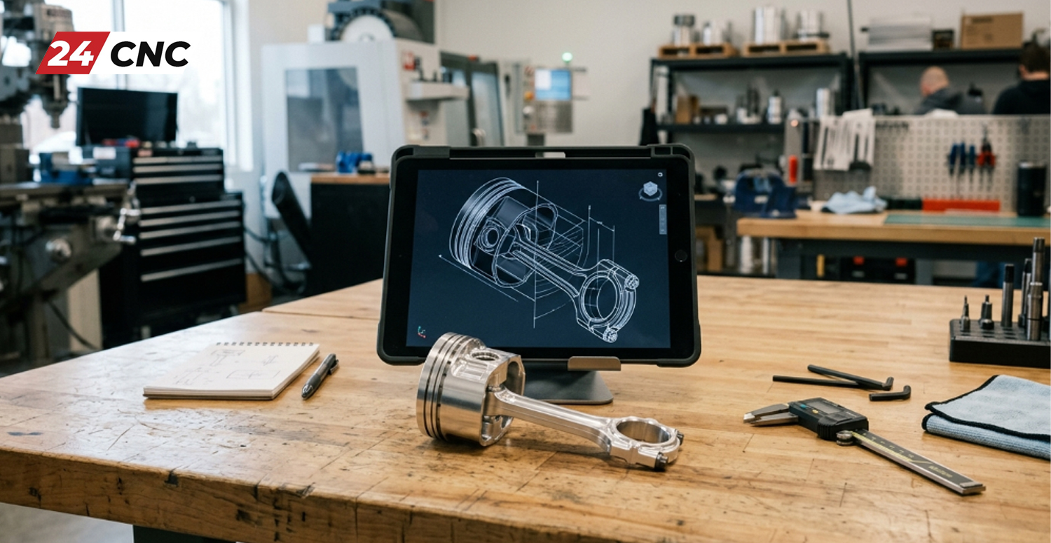
Once the 3D CAD model is finalized and approved, it must be translated into instructions that a machine can execute. A CNC machine does not understand a CAD file natively; it only understands coordinates. This gap is bridged by Computer-Aided Manufacturing (CAM) software.
The CAM programmer imports the 3D model and begins defining the machining strategy. This involves several critical sub-steps:
- Defining the Raw Material (The Stock): The programmer tells the software the dimensions of the raw block of metal or plastic they are starting with.
- Tool Selection: The programmer chooses which specific cutting tools will be used. This might include a large face mill to remove material quickly (roughing), an end mill for cutting slots, and a tiny ball-nose end mill for creating smooth 3D surface finishes.
- Speeds and Feeds: The CAM software calculates—or the programmer manually inputs—the spindle speed (RPM) and the feed rate (how fast the tool moves through the material). These calculations rely heavily on the type of material being cut to prevent the tool from breaking or overheating.
- Generating Toolpaths: The software calculates the most efficient route for the tool to take in order to carve away the excess material.
Step 3: The Language – Post-Processing and G-Code
Once the toolpaths are visually simulated in the CAM software to ensure there are no catastrophic crashes, the data must be output as a text file. This process is called “post-processing.” The post-processor takes the CAM data and converts it into the specific dialect of G-code required by the machine’s controller (such as a Fanuc or Siemens system).
G-code is an alphanumeric programming language. It is the literal heartbeat of the CNC process. A typical G-code file can contain tens of thousands of lines of code. For example, a command like G01 X50.0 Y25.0 F200 tells the machine to move in a straight line to coordinate $X=50$, $Y=25$ at a feed rate of 200 mm/min. Alongside G-code is M-code, which controls hardware functions like turning on the coolant or rotating the tool carousel. To explore how the machine’s brain processes these commands, read what a CNC controller interprets from G-code and M-code.
Step 4: The Foundation – Machine Setup and Workholding
With the program ready on a USB drive or sent via the network, the physical work begins on the shop floor. This phase is handled by a CNC Operator or Setup Machinist.
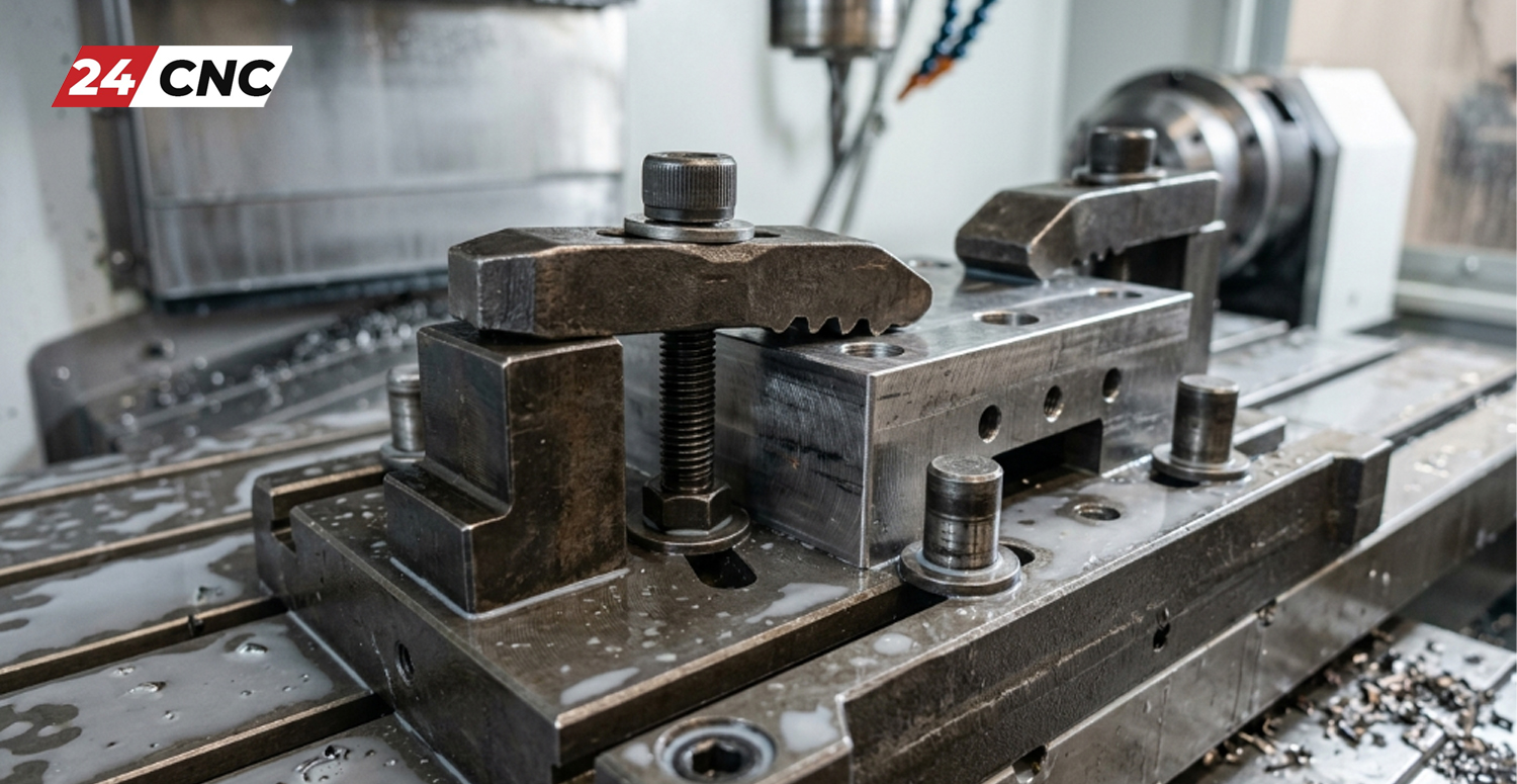
First, the operator must secure the raw material into the machine. This is known as “workholding.” Common workholding devices include heavy-duty machine vises, chucks, or custom-machined fixtures. If the material shifts even a fraction of a millimeter during cutting, the part will be ruined. Therefore, rigid clamping is non-negotiable.
Next, the operator must load all the physical cutting tools into the machine’s automatic tool changer (ATC) and measure their exact lengths and diameters. Finally, the operator establishes the “Work Coordinate System” (WCS). They use probes or edge finders to tell the machine exactly where the top corner of the raw material is located in physical space. This establishes the $X=0, Y=0, Z=0$ point that the G-code will reference. During setup, operators frequently rely on a Manual Pulse Generator (MPG) handwheel to jog the axes precisely by fractions of a millimeter without starting the main program.
Step 5: The Execution – The Machining Process
Once setup is verified, the operator presses cycle start, and the control system takes over. The servo motors roar to life, driving the axes to position the spinning tool against the raw metal. High-pressure liquid coolant blasts onto the cutting zone to clear away chips and keep temperatures down.
The machining phase generally happens in two stages:
- Roughing: The goal here is purely material removal. Large tools take aggressive cuts to carve out the rough shape of the final part as fast as possible. The surface finish is usually poor at this stage.
- Finishing: Smaller, sharper tools come in, taking very light, fast cuts. This removes the remaining few thousandths of an inch of material, bringing the part to its final exact dimensions and leaving a smooth, mirror-like surface finish.
Technical Comparison: Milling vs. Turning
Depending on the part’s shape, the manufacturing process will primarily utilize either a CNC Mill or a CNC Lathe. Here is a breakdown of how they differ:
| Feature / Aspect | CNC Milling | CNC Turning (Lathe) |
|---|---|---|
| Basic Principle | The workpiece is stationary; the cutting tool rotates. | The workpiece rotates rapidly; the cutting tool is stationary. |
| Ideal Part Shapes | Flat, square, asymmetrical, and complex 3D contoured parts (e.g., engine blocks). | Symmetrical, cylindrical, and round parts (e.g., shafts, rings, threaded pipes). |
| Tool Types | End mills, face mills, drill bits, taps. | Insert tools, boring bars, parting tools, threading tools. |
| Axis Movement | Typically 3, 4, or 5 axes of continuous movement. | Typically 2 axes ($X$ and $Z$), though modern mill-turns add more. |
Step 6: Quality Control and Post-Processing
Just because the part comes out of the machine does not mean it is finished. Quality Control (QC) is a massive part of manufacturing. Machinists use precision instruments like micrometers, calipers, and Coordinate Measuring Machines (CMM) to verify that every dimension on the physical part perfectly matches the tolerances dictated back in Step 1 by the CAD model.
Once the part passes inspection, it often moves to post-processing. This step enhances the part’s physical properties or aesthetic appearance. Common post-processing techniques include:
- Anodizing: An electrochemical process that thickens the natural oxide layer on aluminum, preventing corrosion and allowing the part to be dyed vibrant colors.
- Bead Blasting: Shooting fine glass beads at high pressure to remove tooling marks and create a uniform, matte finish.
- Heat Treating: Baking the metal at extreme temperatures to increase its hardness and durability.
- Powder Coating: Applying a dry powder paint that is cured under heat for a tough, protective skin.
The Hardware Making It All Possible
Behind this seamless workflow is a massive ecosystem of specialized hardware. A CNC machine is only as good as the sum of its parts. If a single rotary encoder fails, or if a servo amplifier burns out, the entire manufacturing process halts. Understanding the essential components of a CNC machine is vital for anyone working in this industry, as proactive maintenance and knowing how to source quality replacement electronics is what keeps production lines moving.

Frequently Asked Questions (FAQ)
How long does it take to make a CNC part?
The machining time itself can range from a few minutes for a simple aluminum bracket to dozens of hours for complex, 5-axis aerospace turbine blades made of tough alloys like Inconel. However, the lead time is often dictated by the programming (CAM) and setup times, which can take longer than the actual cutting.
Can CNC machines cut both metal and plastic?
Yes. CNC machines are incredibly versatile. By simply changing the type of cutting tool, adjusting the spindle RPM, and altering the feed rate, the same machine that cuts solid steel can cut soft plastics like Delrin, Acrylic, or Polycarbonate without melting them.
Is 3D Printing better than CNC Machining?
Neither is strictly “better”; they serve different purposes. 3D printing (additive manufacturing) is excellent for rapid prototyping, complex internal lattice structures, and low volume. CNC machining (subtractive manufacturing) is far superior when you require high structural strength, incredibly tight tolerances, superior surface finishes, and scalable mass production.
Keep Your Production Line Moving with 24CNC
The journey from 3D model to finished part relies on machinery that functions flawlessly. When downtime strikes, you need reliable, industrial-grade replacement parts fast. Wondering where to buy high-quality CNC parts online? We’ve got you covered.
Leave a comment
Your email address will not be published. Required fields are marked *