A Guide to CNC Machine Switches, Sensors, and Buttons
In the highly precise world of industrial manufacturing, the raw cutting power of a CNC machine is rendered entirely useless without the complex nervous system that governs its movements and ensures operator safety. This nervous system is comprised of a vast array of input devices: CNC machine switches, sensors, and buttons. From the satisfying tactile click of a cycle start button to the invisible magnetic field of an inductive proximity sensor verifying a tool change, these components are the frontline interface between human intent and mechanical execution.
For engineers designing custom automated cells, procurement specialists sourcing reliable spare parts, and workshop owners fighting to minimize machine downtime, understanding the distinct roles, electrical characteristics, and failure modes of these components is crucial. A single faulty limit switch or a degraded membrane keyboard can halt a multi-million-dollar production line, resulting in massive financial losses and delayed deliveries.
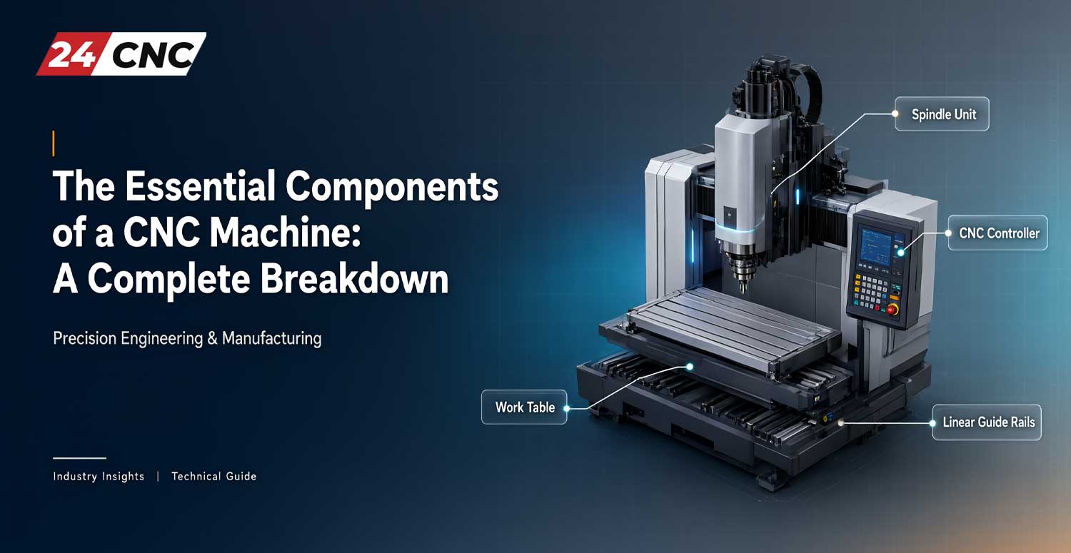
In this authoritative guide, we will dissect the critical input and feedback devices used in modern CNC machining centers and lathes. We will explore the mechanical design of operator panel buttons, the physics behind various industrial sensors, and how these signals are ultimately processed by the machine’s control unit. Furthermore, we will highlight the importance of sourcing premium essential components of a CNC machine to maintain peak operational efficiency.

The Frontline of Control: CNC Machine Buttons and Manual Switches
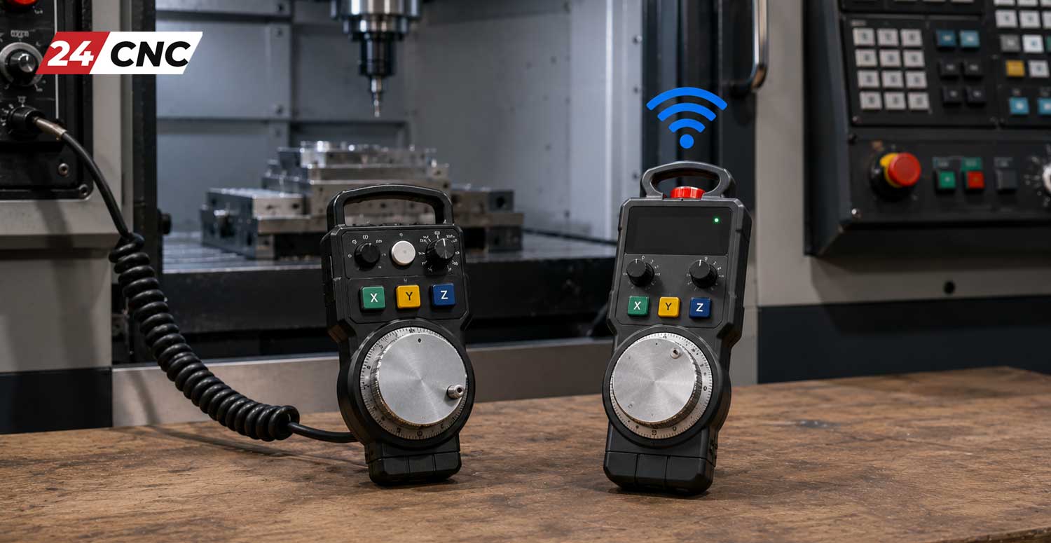
The operator control panel (often referred to as the HMI – Human Machine Interface) is the primary command center of any CNC machine tool. The physical buttons and switches on this panel must withstand incredibly harsh environments, including constant exposure to highly acidic synthetic coolants, metallic dust, lubricating oils, and the heavy-handed repetitive pressing by operators wearing thick industrial gloves.
Emergency Stop (E-Stop) and Safety Critical Buttons
The most critical button on any piece of industrial machinery is the Emergency Stop, or E-Stop. By international safety standards (such as ISO 13850), E-Stops must be highly visible (red mushroom head on a yellow background), easily accessible, and feature a “positive opening” mechanical operation. This means the internal switch contacts are mechanically forced apart when the button is pressed, rather than relying on a small spring that could potentially jam or fail.
When an E-Stop is triggered, it immediately severs the main control voltage to the machine’s servo drives and spindle contactors, engaging mechanical brakes to stop all axes of motion instantly. These buttons are strictly hardwired into the machine’s safety relay circuit, bypassing standard software controls to guarantee an immediate halt regardless of the computer’s state.
Panel Selectors and Rotary Switches
Mode selection and variable overrides are typically handled by rotary panel selectors. These devices allow the operator to cycle through different machine states, such as JOG, MDI (Manual Data Input), MEM (Memory/Auto), or EDIT. Internally, these rotary switches use a series of stacked mechanical cams and electrical contacts. As the knob turns, the cams mechanically open or close specific combinations of electrical circuits, sending a binary or Grey code signal to the controller indicating the selected position.
Similarly, feed rate and spindle speed overrides utilize multi-position rotary switches to allow operators to adjust programmed speeds on the fly in increments (e.g., $10\%$, $50\%$, $100\%$, $120\%$). Upgrading to high-quality OEM replacements ensures that vibrations do not cause the switch to drift between positions, which could inadvertently alter cutting speeds mid-cycle.
Membrane Keyboards and Tactile Interfaces
Modern CNC controllers, particularly those from industry giants like Fanuc and Siemens, heavily utilize membrane keypads for data entry and navigation. A Fanuc keyboard consists of several thin layers: a graphic overlay (the visible buttons), a spacer layer, and a printed circuit layer. When pressed, the flexible top layer deforms, pushing a conductive pad through a hole in the spacer to complete a circuit on the bottom layer.
While membrane keyboards are highly resistant to fluid ingress (IP65 rated or higher), the constant flexing can eventually lead to micro-fractures in the conductive traces, resulting in unresponsive keys. To combat this, high-end machines often utilize tactile dome switches beneath the membrane, providing a distinct physical “click” that confirms the input to the operator and extends the mechanical lifespan of the interface.

The Eyes and Ears of Automation: Industrial CNC Sensors
While buttons rely on manual human input, CNC sensors operate autonomously, providing constant, real-time feedback to the machine controller about the physical state of the environment. Without these sensors, the machine is completely blind, unable to verify if a part is clamped, if a tool is broken, or if an axis has reached its physical limit.
Limit Switches and Mechanical Overtravel Protection
Mechanical limit switches are the oldest and most robust form of positional sensing on a CNC machine. They consist of a heavy-duty actuator arm (often with a small roller wheel) and a set of internal electrical contacts. As the machine axis moves towards its physical limit, a metal ramp (the “dog”) bolted to the moving table physically depresses the limit switch arm.
CNC machines typically use limit switches for two distinct purposes:
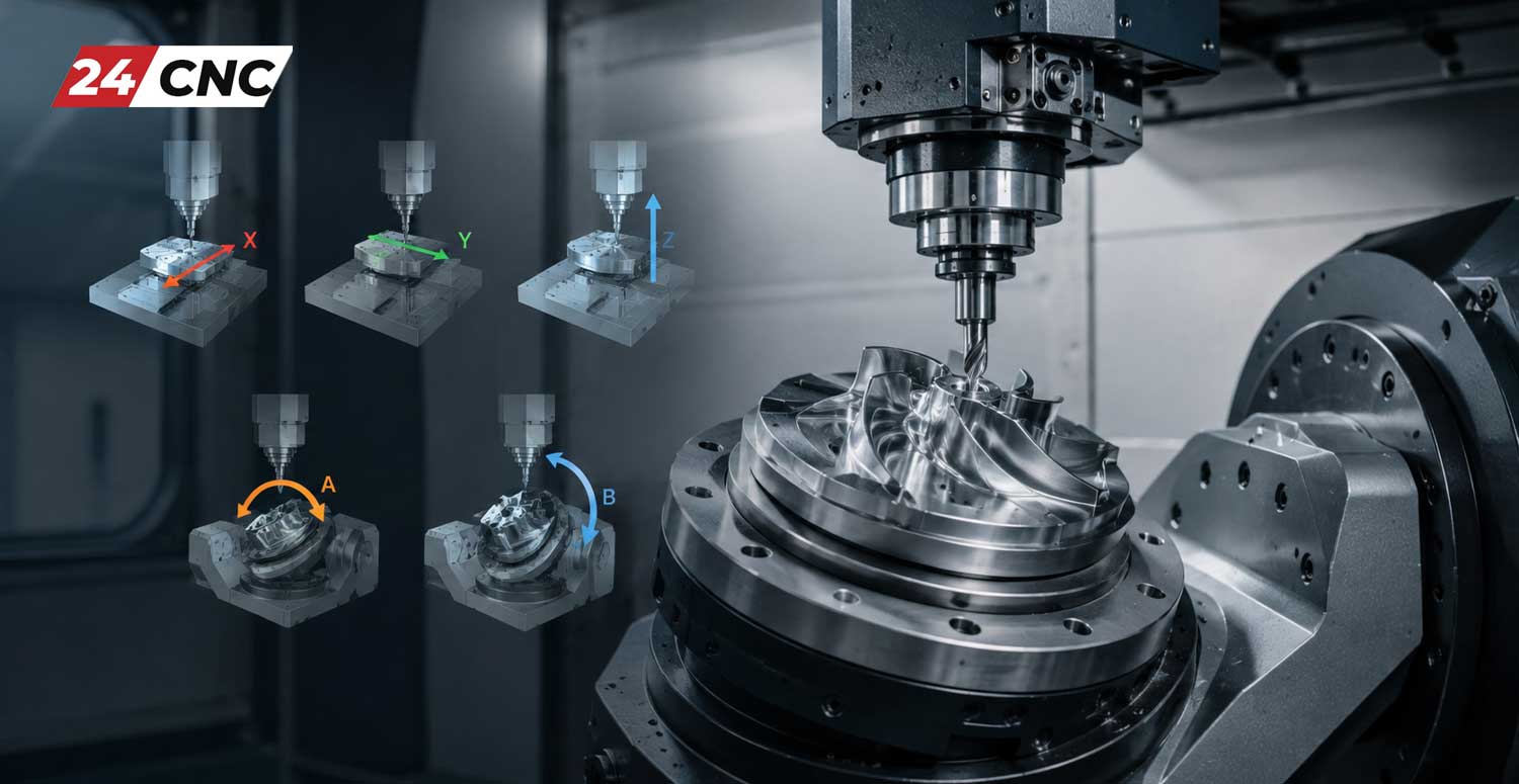
- Reference Return (Homing): When powering up a machine equipped with incremental encoders, the axes must move to a known physical location to establish the $X, Y, Z$ zero coordinate. The axis slowly feeds until it triggers the homing limit switch, establishing the machine datum.
- Hard Overtravel Protection: Located just past the software limits, these switches act as a final safety net. If a servo runaway occurs or the operator makes a massive programming error, hitting the hard overtravel switch instantly triggers an E-Stop condition, preventing the heavy cast-iron table from crashing into the end of the ball screw at rapid traverse speeds.
Proximity Sensors (Inductive and Capacitive)
Unlike mechanical switches, proximity sensors detect the presence of an object without any physical contact, completely eliminating mechanical wear and extending the sensor’s lifespan indefinitely under normal conditions.
Inductive Proximity Sensors are the most common type used in CNC machining. They generate a high-frequency electromagnetic field from their face. When a ferrous metal object (like a steel tool holder or a cast-iron machine part) enters this field, it induces small eddy currents on the surface of the target metal. This draws energy away from the sensor’s internal oscillator circuit. When the amplitude of the oscillation drops below a specific mathematical threshold, the sensor’s internal Schmidt trigger toggles the output state. The standard sensing distance ($S_n$) for these devices is mathematically dependent on the coil diameter and the permeability of the target metal, typically ranging from $1mm$ to $15mm$. These are highly prevalent in tool changers (ATC) to verify that a tool is fully seated in the spindle before the arm retracts.
Capacitive Proximity Sensors work on a similar non-contact principle but measure changes in electrical capacitance. Because they react to changes in the dielectric constant, they can detect both metallic and non-metallic objects. In CNC applications, they are frequently used in coolant tanks to monitor fluid levels or in automated bar feeders to detect the presence of raw plastic or aluminum stock.
Photoelectric and Tool Setting Sensors
Precision is paramount, and optical or photoelectric sensors play a massive role in maintaining tight tolerances. These sensors use a light emitter (often an infrared LED or a focused laser) and a receiver. If the light beam is broken or reflected by an object, the sensor triggers.
Advanced tool setters (like those from Renishaw or Blum) utilize a highly precise kinematic mechanism combined with optical sensing to measure tool length and diameter automatically. When the spinning cutting tool touches the ruby stylus of the setter, it breaks an internal optical beam, sending a high-speed skip signal to the CNC controller. The controller immediately records the exact $Z$-axis position, calculating the tool offset down to a resolution of $0.001mm$. Specialized Fanuc sensors are highly integrated into their proprietary control architecture to ensure these high-speed signals are processed with zero latency.

Bridging the Gap: I/O Modules and Control Integration
Every single button press, limit switch trigger, and sensor activation generates a discrete electrical signal—typically a $24V$ DC voltage. However, the machine’s central processing unit (CPU) operates on low-voltage digital logic (usually $3.3V$ or $5V$ DC). To bridge this critical gap, the machine relies on Input/Output (I/O) modules.
An I/O module acts as the vital translator and protective barrier between the harsh physical world of the machine shop and the delicate digital brain of the CNC controller. When a limit switch closes, $24V$ is sent via a heavy-duty CNC cable to a specific input pin on the module. Internally, the module uses an optoisolator—a tiny LED and a phototransistor—to pass the signal to the CPU using light, entirely isolating the computer from potentially catastrophic voltage spikes or electrical noise generated by the spindle motors.
In massive multi-axis machines, modern architectures use remote distributed I/O blocks connected via high-speed industrial Ethernet (like PROFINET or EtherCAT) rather than running thousands of individual wires back to the main electrical cabinet. This drastically reduces electrical noise, simplifies troubleshooting, and makes upgrading the machine significantly easier.
Technical Comparison Matrix: Industrial Sensors vs. Switches
| Feature | Mechanical Limit Switches | Inductive Proximity Sensors | Photoelectric Sensors |
|---|---|---|---|
| Operation Method | Physical contact (Actuator arm) | Non-contact (Electromagnetic field) | Non-contact (Light beam breaking) |
| Target Material | Any physical solid object | Strictly Metallic (Ferrous/Non-Ferrous) | Any opaque object |
| Lifespan & Wear | Finite (Subject to mechanical fatigue) | Virtually infinite (No moving parts) | High, but lenses require cleaning |
| Response Time | Slow (Depends on spring mechanics) | Extremely Fast ($<1ms$) | Very Fast (Speed of light/processing) |
| Primary CNC Use Case | Hard Overtravel, Door Safety Interlocks | ATC Position Verification, Homing | High-precision Tool Measurement |
Frequently Asked Questions (FAQ)
Why did my CNC machine trigger a “Soft Overtravel” alarm if it hasn’t hit the physical limit switch?
A “soft overtravel” is a digital safety boundary configured within the machine’s parameter settings (software limits). The CNC controller mathematically tracks the axis position via encoders. If the program commands the machine to move past these invisible digital coordinates, it triggers an alarm and stops motion before it ever reaches the physical mechanical limit switch, preventing unnecessary stress on the machine components.
Can I replace a faulty mechanical limit switch with an inductive proximity sensor?
In many positional applications, yes, you can upgrade from a mechanical switch to a solid-state proximity sensor to increase reliability. However, you must carefully check the machine’s electrical schematics. You must match the voltage (typically 24V DC), the output type (NPN vs. PNP), and the logic state (Normally Open – NO, or Normally Closed – NC). Furthermore, hard-wired safety circuits (like E-Stops or door interlocks) often legally require mechanical switches with positive-opening contacts to comply with machine safety directives.
How do I diagnose a malfunctioning CNC membrane keyboard?
If specific buttons on your panel are unresponsive, the issue is typically a severed conductive trace inside the membrane layers caused by repeated flexing or coolant ingress. You can diagnose this by tracing the matrix ribbon cable back to the I/O board and using a multimeter to check for continuity when the key is pressed. If the resistance remains at infinity ($\infty \Omega$) when pressed, the membrane matrix is fundamentally broken and the entire keypad overlay must be replaced with a genuine OEM part.
What does it mean when a sensor is PNP or NPN?
These terms refer to the internal transistor configuration of a DC sensor. A PNP (Sourcing) sensor switches the positive voltage ($+24V$) to the output pin when activated. An NPN (Sinking) sensor connects the output pin to the DC ground ($0V$) when activated. You must ensure the sensor type perfectly matches the input requirements of your specific CNC I/O module; mixing them up will result in the controller failing to read the sensor’s signal, and in rare cases, can cause short circuits.
Restore Total Control to Your CNC Machine
Don’t let a sticky cycle start button, a degraded membrane keyboard, or a faulty proximity sensor bring your production line to a grinding halt. Fast, reliable, and precise inputs are the lifeblood of industrial automation. Browse our massive inventory of genuine, industrial-grade switches, precise optical sensors, and robust I/O components engineered to withstand the harshest shop floor environments.