
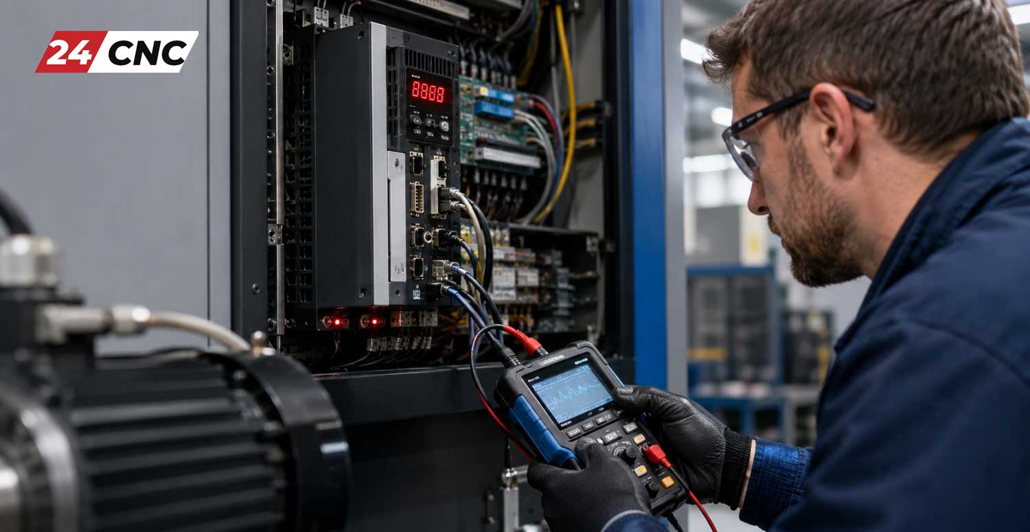
In the high-stakes environment of precision manufacturing, a sudden machine stoppage is a shop owner’s worst nightmare. Among the myriad of potential failures, CNC servo amplifier alarms stand out as some of the most critical and complex issues to resolve. The servo amplifier, often referred to as the servo drive, is the beating heart of your CNC machine’s motion control system, translating low-power command signals from the controller into the high-current power required to move the servo motors precisely.
When this vital component faults, production grinds to a halt. Knowing exactly how to diagnose and troubleshoot CNC servo amplifier alarms can save your facility thousands of dollars in downtime and unnecessary part replacements. This comprehensive guide, tailored for maintenance engineers and workshop technicians, dives deep into the root causes of servo alarms, practical diagnostic steps, and advanced troubleshooting techniques for top brands.
Understanding the Role of the Servo Amplifier in CNC Systems
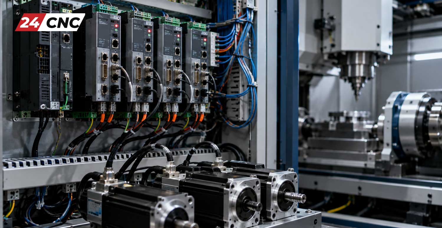
Before diving into diagnostics, it is essential to understand what you are working with. A servo amplifier receives analog or digital signals from the CNC control unit and amplifies them to drive the servo motors. It operates within a closed-loop system, constantly reading feedback from the rotary encoder to adjust current, velocity, and position.
Because these amplifiers and inverters handle high voltages and heavy switching loads, they are susceptible to thermal stress, electrical noise, and component degradation over time. When an anomaly occurs—whether internal to the drive, in the motor, or in the connecting cables—the amplifier triggers a protective alarm to prevent catastrophic damage.
The Most Common CNC Servo Amplifier Alarms and Their Root Causes
Servo alarms are categorized by the specific fault they detect. While the exact error code varies by manufacturer (e.g., Fanuc™, Siemens, Mitsubishi), the underlying electrical principles remain universal.
1. Overcurrent Alarms (OC)
An overcurrent alarm is arguably the most frequent and dangerous fault. It indicates that the current flowing from the amplifier to the motor has exceeded the safe operational threshold. This triggers an immediate emergency stop.
- Short Circuits: The most common cause is a phase-to-phase or phase-to-ground short in the motor windings or the power cables.
- Mechanical Binding: If the machine’s axis is physically jammed (e.g., due to a failed bearing or lack of lubrication), the motor draws excessive current trying to move the load.
- Failed IGBT Module: The Insulated-Gate Bipolar Transistor (IGBT) is the main switching component inside the drive. If an IGBT module shorts internally, it will cause a hard overcurrent alarm the moment power is applied.
2. Overvoltage (OV) and Undervoltage (UV) Alarms
These alarms relate to the DC bus voltage inside the amplifier. In a typical three-phase AC system, the incoming voltage is rectified into DC. You can calculate the expected peak DC bus voltage using the formula $V_{DC} = V_{AC} \times \sqrt{2}$. For a 220V system, this is roughly $311V$ DC.
- Overvoltage: Usually occurs during rapid deceleration. The kinetic energy of the moving mass turns the motor into a generator, sending power back to the drive. If the regenerative discharge resistor is faulty or disconnected, the DC bus voltage spikes, triggering an alarm.
- Undervoltage: Often caused by incoming factory power dips, a blown input fuse, or a failing internal power supply within the drive chassis.
3. Encoder / Feedback Alarms
The amplifier must know the exact position of the motor rotor to commutate properly. If communication is lost, a feedback alarm occurs.
- Cable Degradation: Coolant ingress or continuous flexing in the cable track can break the delicate encoder wires.
- Encoder Failure: The glass scale or internal optics of the encoder may be coated in oil or dust.
4. Overheating / Thermal Alarms
High ambient temperatures or failed cooling components will trigger a thermal fault. Check the electrical cabinet filters and ensure the drive controller cooling fans are spinning freely. A fan that has seized due to bearing failure is a very common culprit.
Step-by-Step Diagnostic Process for CNC Servo Drives
When an alarm occurs, do not immediately start swapping parts. A logical, step-by-step diagnostic approach will isolate the fault efficiently.
Step 1: Document the Alarm Code
Check the CNC control screen or the 7-segment LED display directly on the servo amplifier. Write down the exact alarm code. Cross-reference this code with the manufacturer’s maintenance manual.
Step 2: The Visual and Olfactory Inspection
Power down the machine and perform standard Lockout/Tagout (LOTO) procedures. Wait at least 10 minutes for the internal DC bus capacitors to discharge. Open the cabinet and inspect the drive.
- Look for burnt traces on the circuit boards.
- Check for bulging or leaking capacitors.
- Smell the drive—burnt electronics or ozone are dead giveaways of a catastrophic internal failure.
Step 3: Megger Testing the Motor and Cables
To rule out external shorts (which cause overcurrent alarms), disconnect the motor power cables from the bottom of the servo amplifier. Use an insulation resistance tester (Megger) to test the cables and motor windings to ground. A reading of less than 10 Megohms generally indicates insulation breakdown requiring a motor rebuild or cable replacement.
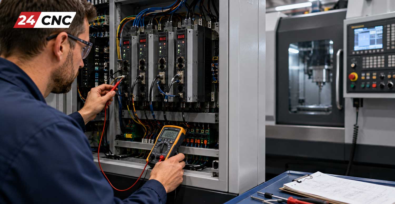
Step 4: Testing the Internal IGBTs with a Multimeter
If the motor and cables test fine, the amplifier itself is likely the culprit. You can perform a static diode test on the IGBT module using a digital multimeter.
- Set the multimeter to “Diode Test” mode.
- Place the positive (red) probe on the negative DC bus terminal, and the negative (black) probe on the U, V, and W motor output terminals successively. You should read a standard diode voltage drop (typically between $0.3V$ and $0.5V$).
- Reverse the probes. The reading should show “OL” (Over Limit or Open Loop).
- Repeat the process relative to the positive DC bus terminal.
If any reading shows $0.00V$ (a dead short) or is significantly different from the others, the IGBT module has failed, and the drive must be repaired or replaced.
Technical Comparison: Brand-Specific Troubleshooting
Different manufacturers have distinct architectures and alarm behaviors. Below is a comparison table outlining how the top three CNC control manufacturers handle servo amplifier faults.
Preventative Maintenance to Avoid Amplifier Failure
The best way to handle servo amplifier alarms is to prevent them from happening. Implement these maintenance strategies in your facility:
- Cabinet Climate Control: Ensure heat exchangers or cabinet AC units are fully functional. Heat degrades internal capacitors rapidly.
- Clean Filters: Replace CNC cabinet air filters monthly to prevent conductive carbon dust from settling on circuit boards.
- Cable Management: Regularly inspect the energy chains (cable tracks) for wear. Replace stiff or brittle cables before they short out.
- Vibration Checks: Ensure the mounting screws on the drive and motor are tight. Vibration can loosen connections, leading to arcing and localized heating.
When to Repair vs. When to Replace
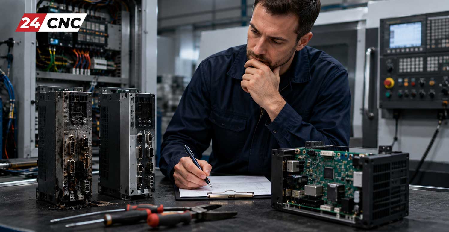
Once you have diagnosed a failed servo amplifier, you face a critical decision: repair or replace?
If the drive is relatively new and suffered a simple component failure (like a blown fan or input bridge rectifier), repairing it at a certified electronics lab is cost-effective. However, if the drive is a legacy unit (15+ years old), internal circuit board traces may be degraded, and sourcing obsolete components can be a nightmare. In such cases, purchasing a refurbished or new replacement unit from a reliable vendor is the fastest way to get your machine back to making chips. When looking for replacements, knowing where to buy high-quality CNC parts online ensures you receive tested, warrantied components rather than risky surplus electronics.
Frequently Asked Questions (FAQ)
Can a faulty servo motor cause a servo amplifier alarm?
Yes. A shorted winding in the servo motor or a contaminated encoder will cause the amplifier to draw excessive current or lose feedback, triggering an overcurrent (OC) or feedback alarm on the drive.
What does it mean when the DC bus voltage drops too low?
An undervoltage alarm usually means the main incoming 3-phase power has dropped, or the internal rectifier bridge/charging circuit inside the drive power supply has failed.
How do I reset a hard servo alarm?
Most minor alarms can be cleared via the “Reset” button on the CNC control panel. However, critical hardware alarms (like Overcurrent) often require completely cycling the main power to the machine. Never repeatedly reset a hard overcurrent alarm without diagnosing it, as this will destroy the amplifier’s internal components.
Is Your CNC Machine Down with a Drive Alarm?
Don’t let a failed servo amplifier ruin your production schedule. At 24CNC, we supply top-tier, rigorously tested servo drives, IGBT modules, cooling fans, and encoders for Fanuc, Siemens, Mitsubishi, and more.
Find Your Replacement Parts Now
Fast Shipping • Quality Guaranteed • Expert Support
Leave a comment
Your email address will not be published. Required fields are marked *