A Guide to Wiring a Rotary Encoder to Arduino and ESP32 for DIY Projects

A Guide to Wiring a Rotary Encoder to Arduino and ESP32 for DIY Projects

Whether you are building a custom menu interface, a robotics project, or designing your own DIY CNC machine, mastering the rotary encoder is a critical skill. Unlike standard potentiometers that have a limited range of motion, rotary encoders can rotate infinitely, providing precise digital feedback regarding position, speed, and direction. This makes them indispensable in modern electronics.

In this comprehensive guide, we will walk you through everything you need to know about wiring, programming, and troubleshooting a rotary encoder using the two most popular microcontrollers in the maker community: the Arduino and the ESP32. We will also explore how these DIY concepts scale up to industrial applications, such as CNC handwheels and automated control systems.

Understanding the Basics: How Does a Rotary Encoder Work?

Before diving into wires and code, it is essential to understand the mechanics behind the hardware. A rotary encoder is an electro-mechanical device that converts the angular position or motion of a shaft into analog or digital output signals.

There are two main types of rotary encoders:

  • Absolute Encoders: These output a unique digital code for every distinct angle of the shaft. They “remember” their position even after a power cycle.
  • Incremental Encoders: These generate a series of pulses as the shaft rotates. They do not know their absolute position upon startup; they only track how far they have moved from a given starting point. This is the most common type used in DIY projects (such as the popular KY-040 module).

The Quadrature Output Explained

Incremental encoders typically utilize a “quadrature” output. Inside the encoder, a slotted disc rotates between light sensors (or mechanical contacts in cheaper models), generating two separate square wave signals, commonly referred to as Channel A (CLK) and Channel B (DT).

These two signals are out of phase by 90 degrees. By analyzing which channel transitions first, the microcontroller can determine the direction of rotation (clockwise or counter-clockwise). By counting the number of pulses, it can determine the distance or angle traveled.

A Guide to Wiring a Rotary Encoder to Arduino and ESP32 for DIY Projects

Essential Components for Your Setup

To follow along with this guide, you will need a few basic components:

  • An Arduino board (e.g., Arduino UNO, Nano) or an ESP32 development board.
  • A Rotary Encoder module (the KY-040 is highly recommended for beginners as it includes built-in pull-up resistors).
  • Jumper wires.
  • A breadboard.
  • Optional but recommended: Capacitors ($0.1\mu F$) and resistors ($10k\Omega$) for hardware debouncing, and a high-quality encoder cable to prevent signal noise if placing the encoder far from the board.

Wiring a Rotary Encoder to an Arduino

The Arduino UNO is an excellent starting point for reading encoder signals. While you can read the signals using standard digital polling, using Interrupts is highly recommended to ensure you never miss a pulse, even if the Arduino is busy processing other code.

Arduino Pinout and Connection Diagram

Assuming you are using a standard KY-040 rotary encoder module, the wiring to the Arduino is as follows:

  • GND: Connect to Arduino GND.
  • + (VCC): Connect to Arduino 5V.
  • SW (Switch): Connect to Digital Pin 4 (This is the push-button feature of the encoder).
  • DT (Data / Channel B): Connect to Digital Pin 3.
  • CLK (Clock / Channel A): Connect to Digital Pin 2.

Note: Pins 2 and 3 on the Arduino UNO support hardware interrupts, which is why we route the DT and CLK signals to them.

Example Arduino Code (Using Interrupts)

Here is a robust code snippet that uses hardware interrupts to track the encoder’s position accurately:

#define CLK_PIN 2
#define DT_PIN 3
#define SW_PIN 4

volatile int encoderPosition = 0;
int lastPosition = 0;

void setup() {
Serial.begin(9600);
pinMode(CLK_PIN, INPUT_PULLUP);
pinMode(DT_PIN, INPUT_PULLUP);
pinMode(SW_PIN, INPUT_PULLUP);

// Attach interrupt to the CLK pin
attachInterrupt(digitalPinToInterrupt(CLK_PIN), updateEncoder, CHANGE);
}

void loop() {
if (encoderPosition != lastPosition) {
Serial.print(“Position: “);
Serial.println(encoderPosition);
lastPosition = encoderPosition;
}

if (digitalRead(SW_PIN) == LOW) {
Serial.println(“Button Pressed!”);
delay(200); // Simple debounce
}
}

void updateEncoder() {
int dtValue = digitalRead(DT_PIN);
int clkValue = digitalRead(CLK_PIN);

if (clkValue == dtValue) {
encoderPosition++;
} else {
encoderPosition–;
}
}

Wiring a Rotary Encoder to an ESP32

The ESP32 is significantly more powerful than the standard Arduino UNO. It operates on a 3.3V logic level, meaning you must power your encoder with 3.3V, NOT 5V, to avoid damaging the GPIO pins.

ESP32 Pinout and Connection Diagram

  • GND: Connect to ESP32 GND.
  • + (VCC): Connect to ESP32 3.3V.
  • SW (Switch): Connect to GPIO 25.
  • DT (Data / Channel B): Connect to GPIO 26.
  • CLK (Clock / Channel A): Connect to GPIO 27.

Note: Almost all GPIO pins on the ESP32 support interrupts, giving you much more flexibility in your wiring layout.

Example ESP32 Code

While you can use the exact same interrupt logic as the Arduino, the ESP32 is fast enough to handle standard hardware interrupts seamlessly. Here is the adapted code for the ESP32:

#define CLK_PIN 27
#define DT_PIN 26
#define SW_PIN 25

volatile int encoderCounter = 0;
int lastCounter = 0;
portMUX_TYPE mux = portMUX_INITIALIZER_UNLOCKED;

void IRAM_ATTR isr() {
portENTER_CRITICAL_ISR(&mux);
int dtVal = digitalRead(DT_PIN);
int clkVal = digitalRead(CLK_PIN);

if (clkVal == dtVal) {
encoderCounter++;
} else {
encoderCounter–;
}
portEXIT_CRITICAL_ISR(&mux);
}

void setup() {
Serial.begin(115200);
pinMode(CLK_PIN, INPUT_PULLUP);
pinMode(DT_PIN, INPUT_PULLUP);
pinMode(SW_PIN, INPUT_PULLUP);

attachInterrupt(digitalPinToInterrupt(CLK_PIN), isr, CHANGE);
}

void loop() {
if (encoderCounter != lastCounter) {
Serial.print(“ESP32 Encoder Position: “);
Serial.println(encoderCounter);
lastCounter = encoderCounter;
}
}


The Critical Importance of Debouncing

Mechanical rotary encoders suffer from a phenomenon known as “contact bounce.” When the metal contacts inside the encoder touch and separate, they can bounce on a microscopic level, creating multiple false signals in a fraction of a millisecond. If left untreated, your microcontroller will count these bounces as actual rotations, leading to wild and erratic readings.

Software Debouncing

Software debouncing involves ignoring any signals that occur within a few milliseconds of each other. While the `delay()` function works for basic buttons, it ruins the fast responsiveness required for encoders. Instead, timing functions like `millis()` should be used to filter out noise.

Hardware Debouncing (RC Filter)

The most reliable method is implementing a hardware RC (Resistor-Capacitor) low-pass filter on the CLK and DT lines. By adding a $10k\Omega$ resistor in series and a $0.1\mu F$ capacitor to ground, you smooth out the erratic voltage spikes.

The cutoff frequency for this RC filter can be calculated using the formula:

$$f_c = \frac{1}{2 \pi R C}$$

With a $10k\Omega$ resistor and a $0.1\mu F$ capacitor, the cutoff frequency is approximately $159 Hz$, effectively filtering out the high-frequency mechanical bounce while allowing human-speed rotations to pass through perfectly.

A Guide to Wiring a Rotary Encoder to Arduino and ESP32 for DIY Projects

Applications: From Simple DIY to Industrial CNC Handwheels

Once you understand how to interface a basic KY-040 encoder with a microcontroller, a massive world of applications opens up. In simple DIY electronics, encoders are used for volume knobs, menu navigation screens, and robotic wheel odometry.

However, the exact same underlying principles apply to industrial manufacturing and CNC machining. In the professional realm, rotary encoders are scaled up into heavy-duty Manual Pulse Generators (MPGs) or handwheels. These industrial handwheels allow machinists to manually position heavy CNC axes with micrometer precision.

While a DIY Arduino project uses a $2 encoder, an industrial control system might rely on a high-precision Fanuc encoder that outputs thousands of pulses per revolution (PPR) via differential signals (RS422) for extreme noise immunity over long cable runs. Despite the difference in scale and price, the core concept of counting quadrature pulses remains identically rooted in the logic you just learned.

Technical Comparison: Arduino vs. ESP32 for Encoder Interfacing

Which microcontroller is best for your encoder project? Review this technical breakdown to decide.

Feature Arduino UNO ESP32
Operating Voltage 5V Logic 3.3V Logic
Hardware Interrupt Pins Only Pins 2 & 3 Almost all GPIOs
Clock Speed 16 MHz 160 – 240 MHz
Hardware Pulse Counter (PCNT) No Yes (Dedicated hardware subsystem)
Best Use Case Simple menus, basic DIY robotic feedback. High-speed rotational tracking, complex CNC interfaces, IoT remote monitoring.

Frequently Asked Questions (FAQ)

Why is my rotary encoder skipping values or counting backwards?

This is almost always caused by mechanical switch bounce. When you rotate the encoder, the internal contacts bounce, creating false signals. You must implement either software debouncing using a timing variable or, ideally, hardware debouncing using a small capacitor and resistor on the output pins.

Can I use a 5V encoder on the ESP32?

The ESP32 has a strictly 3.3V logic level limit. Connecting a 5V signal directly to an ESP32 GPIO pin can permanently damage the board. You must either power the encoder with 3.3V (most KY-040 modules work fine at 3.3V) or use a logic level converter.

How do I read a high-resolution industrial encoder with an Arduino?

High-resolution encoders output pulses much faster than a standard Arduino can read via basic interrupts. For industrial encoders (e.g., 2000+ PPR), you will need dedicated quadrature decoder ICs (like the LS7366R) or a much faster microcontroller like an ESP32 utilizing its dedicated PCNT (Pulse Counter) hardware peripheral.

Conclusion

Wiring and programming a rotary encoder with an Arduino or ESP32 is a fantastic way to introduce precise control and feedback into your DIY projects. By understanding quadrature signals, utilizing hardware interrupts, and effectively debouncing the output, you can create smooth, professional-feeling interfaces.

The skills you learn manipulating simple DIY encoders are highly transferable. The logic remains exactly the same whether you are turning down the volume on a custom Bluetooth speaker or dialing in the Z-axis on a massive industrial CNC milling machine.

Ready to Upgrade Your CNC Projects?

Whether you are transitioning from Arduino prototypes to professional builds, or repairing high-end industrial machinery, precision is everything. Explore our extensive catalog of genuine, high-performance CNC electronics and rotary encoders.

Shop Industrial Rotary Encoders Today

an Encoder

What is an Encoder and Why is it Critical for CNC Servo Motors?

In the high-stakes world of CNC machining, where precision is measured in microns and downtime costs thousands per hour, the servo motor is often hailed as the “muscle” of the machine. However, a muscle is useless without a nervous system to tell it where to move, how fast to go, and when to stop. This is exactly what an encoder is.

The encoder is the unsung hero of industrial automation—a sophisticated sensor that translates mechanical motion into electrical signals. Without it, your expensive CNC machine is essentially blind. Whether you are running a generic setup or a high-end system with a Fanuc controller, understanding the role of the encoder is essential for troubleshooting, maintenance, and optimizing performance.

In this comprehensive guide, we will dissect the anatomy of an encoder, explore the critical differences between incremental and absolute technologies, and explain why the feedback loop is the heartbeat of modern manufacturing.

an Encoder

The Core Definition: What Does an Encoder Actually Do?

At its simplest level, a rotary encoder is an electro-mechanical device that converts the angular position or motion of a shaft into an analog or digital code. When attached to a servo motor, it monitors the motor’s shaft rotation and sends that data back to the CNC control system (the brain).

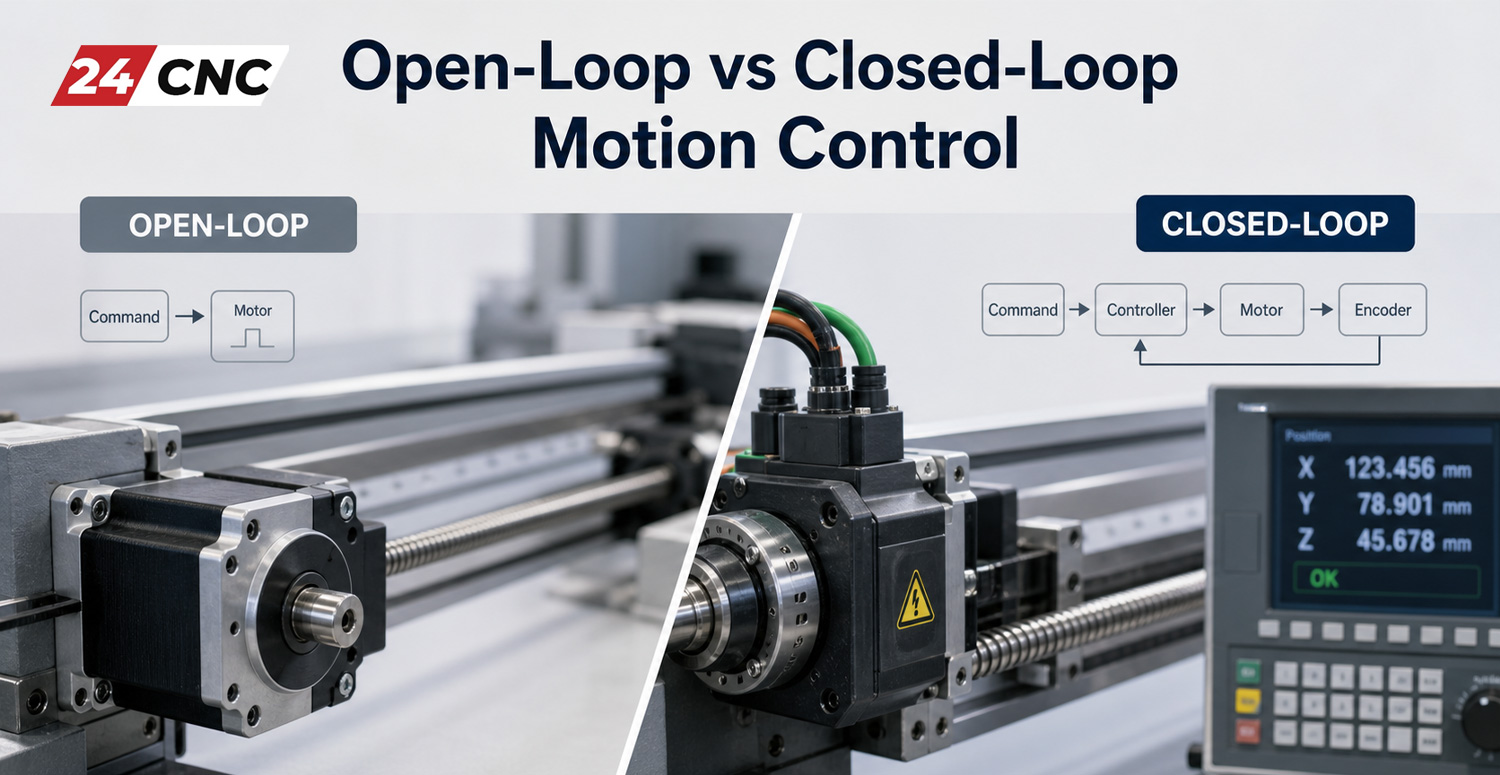
Think of the CNC controller as a captain shouting orders (“Move the X-axis 100mm!”). The servo motor is the crewman pulling the rope. The encoder is the observer who watches the rope and yells back, “We have moved exactly 99.8mm… okay, now 100mm!” This process creates what is known as a Closed-Loop System.

The Three Vital Data Points

A functioning encoder provides the CNC system with three critical pieces of information:

  1. Position: Exactly where the tool is located on the axis.
  2. Speed: How fast the motor shaft is spinning.
  3. Direction: Whether the axis is moving forward (Clockwise) or backward (Counter-Clockwise).

How Encoders Create the “Closed-Loop” Advantage

Standard stepper motors operate on an “open-loop” system—the controller sends a pulse and hopes the motor moves. If the tool hits a hard spot in the metal and the motor stalls, the controller never knows, leading to ruined parts.

Servo systems, utilized by top brands like Mitsubishi and Siemens, rely on the encoder for error correction. The signal travels from the encoder, through the encoder cable, to the servo drive (amplifier).

  • Command vs. Reality: The amplifier and inverter compare the commanded position from the CNC to the actual position reported by the encoder.
  • Instant Correction: If there is a discrepancy (error), the drive instantly adjusts the voltage and current to the motor to snap it back into the correct position. This happens thousands of times per second.

an Encoder

Types of Encoders: Incremental vs. Absolute

When selecting a motor or a replacement part, you will inevitably face the choice between two primary technologies. Understanding the difference is crucial for machine setup.

1. Incremental Encoders

An incremental encoder measures change in position. It generates a continuous stream of pulses as the shaft rotates. It essentially says, “I moved one step… I moved another step.”

The Catch: It does not know where it is when the power is turned off. Every time you power up a CNC machine with incremental encoders, you must perform a “Homing” or “Reference Return” procedure so the machine can find its zero point.

2. Absolute Encoders

An absolute encoder, commonly found in modern Fanuc encoders, assigns a unique digital code to every distinct angle of the shaft. It knows exactly where it is at all times.

The Advantage: Even if the power is cut, the encoder remembers its position (often assisted by a battery backup). When you restart the machine, you can start machining immediately without homing the axes.

Optical vs. Magnetic vs. Capacitive Sensing

How does the encoder actually “see” the movement? There are three main technologies used inside the housing:

  • Optical Encoders: These use a light source (LED) and a photodetector separated by a spinning glass or plastic disk with fine lines on it. As the disk spins, it interrupts the light beam, creating pulses. These are highly accurate but sensitive to dust and vibration. High-precision units often found in Tamagawa products usually employ optical technology.
  • Magnetic Encoders: These use a magnet attached to the rotating shaft and a sensor that detects changes in the magnetic field. They are incredibly rugged and resistant to oil, dirt, and vibration, making them ideal for harsh environments.
  • Capacitive Encoders: Similar to digital calipers, these measure changes in capacitance. They offer a good balance of durability and accuracy.

an Encoder

Critical Components that Support the Encoder

An encoder does not work in isolation. For the signal to remain pure and the machine to function, the supporting hardware must be in top condition.

The Cables

The signal generated by an encoder is low voltage and highly susceptible to electrical noise (EMI). High-quality, shielded optical cables or copper twisted-pair cables are mandatory. A frayed cable is the #1 cause of “ghost” alarms where the machine errors out for no apparent reason.

The Coupling

The encoder is usually attached to the motor shaft via a flexible coupling. If this coupling slips or breaks, the motor will spin, but the encoder won’t record it. This causes a “Following Error” or “Runaway” condition where the control system shuts down the machine to prevent damage.

Technical Comparison: Incremental vs. Absolute

Feature Incremental Encoder Absolute Encoder
Position Memory Lost on power loss Retained after power loss
Homing Required? Yes, every startup No (Immediate operation)
Output Signal Continuous pulses (A/B/Z channels) Unique binary word/bit-stream
Cost Generally Lower Higher
Common Use Case Conveyors, simple automation, older CNCs Robotic arms, modern CNC mills/lathes

Frequently Asked Questions (FAQ)

Can I replace an absolute encoder with an incremental one?

Generally, no. The servo motor drive and the CNC controller are programmed to expect a specific type of signal protocol. Switching types would require replacing the drive and reprogramming the system.

Why do I get a “Battery Low” alarm on my CNC?

This refers to the battery backup for an Absolute Encoder. If this battery dies while the machine is off, the encoder will lose its position data, and you will have to perform a complex zero-point return calibration. Always replace these batteries promptly.

How do I know if my encoder is bad?

Common symptoms include: the axis oscillating or “jittering” while stopped, “feedback error” alarms, runaway axis movement, or rough motion during cuts. Often, the issue is actually a dirty connector or a bad drive-side connector rather than the encoder itself.

What is resolution in an encoder?

Resolution defines how many “slices” the encoder divides one revolution into. A higher resolution encoder allows the CNC machine to make smoother movements and hold tighter tolerances. Modern Mitsubishi encoders often have resolutions in the millions of pulses per revolution.

Conclusion: Precision Starts Here

The encoder is the bridge between the digital world of G-Code and the physical world of cutting metal. Whether you are maintaining a legacy machine with Yaskawa components or building a new system, ensuring your encoders are healthy and correctly specified is the key to profitability.

Is Your CNC Losing Precision?

A failing encoder leads to scrapped parts and costly downtime. We stock a massive inventory of authentic replacement encoders for Fanuc, Mitsubishi, Siemens, and more.

Find Your Replacement Encoder

Test a Servo Motor and Encoder

How to Test a Servo Motor and Encoder with a Multimeter (Step-by-Step)

In the world of CNC machining and industrial automation, the servo motor is the muscle, and the encoder is the nervous system. When your machine crashes or throws an alarm, knowing how to test a servo motor and encoder with a multimeter is a critical skill. It can save you thousands of dollars in unnecessary replacement parts and hours of diagnosing the wrong component.

Whether you are dealing with a standard industrial setup or specific systems like Fanuc or Mitsubishi, the fundamental electrical principles remain the same. This guide will walk you through the static and dynamic tests you can perform using a standard digital multimeter to determine if your servo motor or encoder is dead or salvageable.

Safety First: Preparation Before Testing

Before touching any terminals, safety is paramount. Servo drives contain capacitors that store high voltage even after power is removed.

  • Power Down: Turn off the main breaker to the CNC machine.
  • Discharge: Wait at least 5 to 10 minutes for the internal capacitors in the amplifier and inverter modules to discharge.
  • Disconnect: Physically disconnect the power cables (UVW) and the feedback cables from the drive side to isolate the motor.

Test a Servo Motor and Encoder

Part 1: How to Test Servo Motor Windings

The servo motor itself is a 3-phase AC permanent magnet motor. The most common failures are shorted windings, open windings, or a ground fault (short to the case). Here is how to check them.

1. Testing Winding Resistance (Phase-to-Phase)

Set your multimeter to the lowest Ohms (Ω) setting. You will be measuring the resistance between the three power leads: U, V, and W.

  1. Measure resistance between U and V.
  2. Measure resistance between V and W.
  3. Measure resistance between W and U.

The Verdict: The readings should be very low (usually between 0.5 Ω and 5.0 Ω depending on motor size) and, most importantly, balanced. If you read 1.2 Ω on U-V but 40 Ω or “OL” (Open Loop) on V-W, the motor windings are burnt or broken. If you need a replacement, browse our catalog of servo motors.

2. Testing Insulation (Phase-to-Ground)

This checks if the internal insulation has melted, causing the copper winding to touch the motor casing.

  1. Set your multimeter to the highest resistance setting (Mega Ohms) or use a dedicated Megohmmeter for better accuracy.
  2. Place the black probe on the Motor Case (ground) or the green ground wire.
  3. Touch the red probe to the U, V, and W terminals sequentially.

The Verdict: You want to see “OL” or infinity. A reading below 10 Megohms usually indicates broken insulation or contamination by coolant. This is a common killer of Fanuc servo motors in older CNC mills.

Test a Servo Motor and Encoder

Part 2: How to Test the Servo Encoder

Testing an encoder with a standard multimeter is more limited than using an oscilloscope, but you can verify basic functionality. An encoder failure usually manifests as a “feedback error” or “position deviation” alarm on the control system.

1. Checking Voltage Supply

Most encoders require a clean 5V DC or sometimes 24V DC power supply to operate.

  • With the machine powered on (but servo off/emergency stop active), locate the encoder pinout.
  • Measure DC Voltage between the +5V (or VCC) and 0V (GND) pins on the connector.
  • If you have 0V, the issue might be the encoder cable or the drive’s power output, not the encoder itself.

2. Incremental Encoder Signal Test

If you have an incremental encoder (common on older Yaskawa or generic setups), you can check the pulse output.

  1. Set the multimeter to DC Volts.
  2. Connect probes to Channel A (or B) and Ground.
  3. Slowly rotate the motor shaft by hand.
  4. You should see the voltage toggle between High (approx 5V) and Low (approx 0V). If the voltage stays constant at 5V or 0V while spinning, the channel is dead.

Note: Serial/Absolute encoders (like those found on modern Mitsubishi encoders) communicate via data packets. A multimeter shows a fluctuating average voltage (usually around 2.5V), but this does not guarantee the data is correct.

Don’t Forget the Cables

Often, the motor and encoder are fine, but the cables moving in the drag chain have snapped internally. Always perform a continuity test on your power and encoder cables from end-to-end while wiggling them to detect intermittent breaks.

Test a Servo Motor and Encoder

Troubleshooting Summary Table

Component Test Method Healthy Result Faulty Result
Motor Windings (U-V-W) Resistance (Ohms) Balanced Low Resistance (e.g., 1.5Ω across all pairs) Open (OL) or Imbalanced (>10% difference)
Motor Ground Insulation Test Infinite (OL) or >100 MΩ Continuity or Low Resistance (<1 MΩ)
Encoder Power DC Voltage Steady 5V or 24V 0V or erratic voltage
Encoder Signal DC Volts (Slow Turn) Toggles High/Low (Incremental) Stuck High or Low

Frequently Asked Questions (FAQ)

Can I test a servo motor by connecting it directly to AC power?

No! Never connect a servo motor directly to mains voltage. Servo motors require a specific drive/amplifier to commutate the phases. Connecting it directly will likely destroy the magnets and burn the windings.

Why does my servo motor smell like ozone?

An ozone or burning smell usually indicates a short circuit within the windings or the insulation breaking down. If you smell this, perform an insulation resistance test immediately and check the cooling fan to ensure the motor wasn’t overheating.

Can I repair a broken encoder myself?

Generally, no. Encoders rely on precise optical disks or magnetic scales aligned to the micron. Disassembling an encoder usually results in losing the commutation alignment. It is safer to buy a replacement rotary encoder that matches your specifications.

What if the motor tests good but the drive still alarms out?

If the motor and cable verify as healthy, the issue is likely the drive itself. The IGBTs (power transistors) inside the drive may be blown. You can check our stock of IGBT modules or consider replacing the entire Fanuc drive unit.

Need Replacement Parts Fast?

If your diagnostic tests confirm a dead motor or encoder, don’t let machine downtime eat your profits. We stock a vast range of CNC parts ready for immediate shipping.

Browse Servo Motors & Encoders

CNC Controller Errors

Troubleshooting Common CNC Controller Errors and Alarms

In the world of precision manufacturing, a CNC machine is the heartbeat of production. When that heartbeat skips—signaled by a flashing red light or an ominous error code—productivity grinds to a halt. Troubleshooting CNC controller errors and alarms is a critical skill for machinists, maintenance technicians, and shop floor managers. Downtime costs money, and understanding how to quickly diagnose and resolve these issues is the difference between a profitable shift and a missed deadline.

At 24cnc.com, we understand the urgency of getting your machine back online. Whether you are dealing with a legacy Fanuc system or a modern Siemens interface, this guide will walk you through the logic of CNC troubleshooting, common failure points, and how to source the right replacement parts.

Understanding the Anatomy of a CNC Alarm

Before diving into specific hardware fixes, it is essential to understand what your CNC control system is trying to tell you. Alarms are generally categorized into three levels of severity:

  • P/S Alarms (Program/Stop): Usually related to G-code syntax errors or programming logic. These stop the cycle but rarely indicate hardware failure.
  • Servo/Spindle Alarms: These indicate issues with the motion control loop, involving motors, encoders, or drives.
  • System Alarms: The most critical category, often pointing to mainboard failures, memory corruption, or severe communication breakdowns.

CNC Controller Errors

Top 5 Most Common CNC Controller Issues (and Fixes)

1. Servo Drive and Motor Alarms (Overtravel & Overload)

Servo alarms are perhaps the most frequent headaches in CNC machining. An “Overload” alarm typically means the motor is drawing too much current, while an “Overtravel” alarm indicates the axis has moved beyond its software or hardware limits.

Troubleshooting Steps:

  1. Mechanical Load: Check the axis for mechanical binding. Is the way lubrication sufficient? Is there debris blocking the path?
  2. Feedback Loop: A faulty rotary encoder can send erratic signals to the controller, causing it to think the motor is moving incorrectly. If the position display jumps or drifts, the encoder or the encoder cable is often the culprit.
  3. Amplifier Issues: If the motor is cool but the alarm persists, the servo amplifier may have a blown internal transistor (IGBT) or a control circuit failure.

2. Power Supply Unit (PSU) Failures

A CNC controller requires stable DC voltage (usually 24V and 5V) to operate its logic circuits. If the screen is blank or the control won’t boot, look at the power supply first.

What to Check:

  • Inspect the power supply unit for LED status lights. A red LED usually indicates a fault.
  • Check input voltages. Is the shop power stable?
  • Blown Fuses: Check the fuses on the power unit and the input stage. A blown fuse often saves the expensive mainboard from surges, but it blew for a reason—check for short circuits before replacing.

3. Overheating and Cooling System Failures

CNC cabinets are hot environments. Dust, oil mist, and heat are the enemies of electronics. Overheating alarms often trigger during long production runs in the summer.

The Fix: Ensure the cabinet cooling fans are operational. If a fan on a specific drive (like a Fanuc drive) fails, the drive will trigger a heat alarm to protect itself. Regularly cleaning the heat sinks and replacing worn-out fans is cheap insurance against drive failure.

4. Communication and Data Transfer Errors

Modern CNCs rely heavily on fast data transfer between the CNC, the PLC, and the drives. Fiber optic communication allows for high speed but introduces fragility.

  • Optical Cables: If you are seeing communication alarms (often “Ring Error” on Fanuc systems), inspect your optical cables. These cables cannot be bent sharply; a kink can break the glass fiber inside.
  • I/O Modules: If specific switches or sensors aren’t registering, the issue might lie in the I/O module connecting the peripheral devices to the main CPU.

5. HMI and Control Panel Glitches

Sometimes the machine runs fine, but you can’t input data or see the screen. Cracked screens or unresponsive keys are common wear-and-tear items.

If the display is dim or flickering, the backlight on the LCD panel may be failing. If buttons require hard pressing to register, the membrane keyboard likely needs replacement. These are relatively easy fixes that restore the “feel” of a new machine.

CNC Controller Errors

Brand-Specific Troubleshooting: Fanuc vs. Siemens vs. Mitsubishi

While the physics of machining doesn’t change, the language of the controller does. Here is how to approach the giants of the industry.

Decoding Fanuc Error Codes

Fanuc systems are known for their reliability but also their cryptic codes. A Fanuc controller often displays codes like “401 Servo Alarm” (VRDY Off). This usually means the drive isn’t ready. This could be a lack of 100V input to the drive or a loose drive-side connector.

Siemens Sinumerik Diagnostics

The Siemens controller ecosystem is powerful. Use the “Diagnostics” button on the panel. The diagnostic buffer creates a time-stamped log of events. Look for “Drive Faults” which often point to the motor or the specific power module.

Mitsubishi Magic

Mitsubishi controls often use 7-segment LED displays on the drives themselves. A generic alarm on the screen might just say “Servo Error,” but the physical drive inside the cabinet will display “32” (Overcurrent) or “10” (Undervoltage). Always check the physical Mitsubishi drive display for the real story.

Technical Comparison: Common Error Indicators

Error Type Fanuc Indicator Siemens Indicator Mitsubishi Indicator Likely Culprit
Battery Low APC Alarm 300/306 Alarm 2100/2101 System Error 9F Absolute Pulse Coder Battery
Servo Overheat Alarm 400 / HC LED Alarm 25000 Display ’46’ Cooling Fan or Motor Load
Communication Alarm 900+ (FSSB) Bus Error / Profibus Abnormal Communication Optical Cable or I/O Board
Spindle Error Alarm 749 / 750 Axis Spindle Fault AL. 20 (Motor side) Sensor or Inverter IGBT

CNC Controller Errors

Hardware vs. Software: Isolating the Problem

One of the biggest challenges is determining if an alarm is a hardware failure or a parameter/software glitch.

Checking the Peripherals

Before ordering a mainboard, check the “cheap” items. Is the handwheel (MPG) functioning? Sometimes a stuck button on a handwheel unit can lock up the system, making it look like a controller freeze. Similarly, check the switches on the panel. A stuck cycle start or feed hold button can mimic software errors.

Memory and Cards

If you are experiencing random crashes or “Parity Errors,” your memory card might be corrupt. Whether you use a PCMCIA adapter or a Compact Flash (CF) card for program transfer, try formatting the card or replacing the adapter to rule out data corruption.

Frequently Asked Questions (FAQ)

How do I reset a battery alarm on a Fanuc CNC?

Battery alarms (like APC 300) mean the backup battery for the absolute position encoder is low. Do not turn off the machine power completely while replacing these batteries, or you will lose the machine’s home position. Replace the batteries (usually located on the Fanuc motor pulse coder or the servo amplifier unit) while the machine is powered on.

My CNC monitor is black, but the machine turns on. What is wrong?

This is often a backlight failure or a loose video cable. If you can see a very faint image when shining a flashlight on the screen, the backlight inverter or the LCD panel itself needs replacement. If there is no image at all, check the power cables going to the screen unit.

What causes a “Servo Lag” or “Following Error”?

This error occurs when the actual position of the motor lags behind the commanded position from the controller. This is frequently caused by excessive friction (lack of lubrication), a heavy cut, or a worn-out servo motor that has lost torque. It can also be a tuning issue in the drive parameters.

Need Replacement CNC Parts Fast?

Don’t let controller errors stall your production line. From Fanuc servo amplifiers to Siemens control panels and hard-to-find cables, we have the inventory to get you back up and running.

Browse Control Systems & Parts


Search for products

Back to Top
Product has been added to your cart