
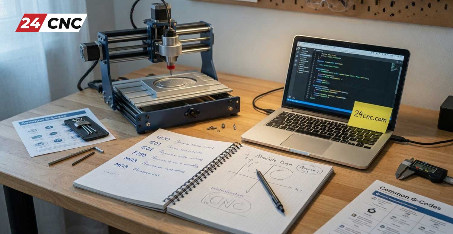
Stepping into the world of industrial automation and modern machining can feel incredibly overwhelming at first glance. Watching massive, multi-ton milling machines and lathes carve out intricate geometries from solid blocks of titanium or steel with micron-level precision is nothing short of mesmerizing. However, behind the roar of the spindles and the spray of the coolant lies a silent, highly logical orchestrator: CNC programming. If you are an aspiring machinist, a manufacturing engineer, a workshop owner, or simply an enthusiast looking to break into this lucrative field, understanding how to communicate with these machines is your first and most crucial step.
In this comprehensive pillar page, we will demystify the language of industrial manufacturing. We will start from the absolute basics—assuming you have zero prior experience—and gradually build your knowledge base. By the end of this guide, you will understand how machines perceive space, how to read and write basic code, and the differences between manual programming and modern software-driven approaches.
What is CNC Programming and Why is it the Future of Manufacturing?
The acronym CNC stands for Computer Numerical Control. Before the advent of computers, machinists operated manual mills and lathes using handwheels, relying heavily on their physical skill, extreme focus, and years of muscle memory to cut parts to size. The introduction of CNC technology revolutionized this process. Instead of a human turning a wheel, servo motors and drive systems move the machine’s axes. But these motors need instructions—they need to know exactly how far to move, at what speed, and in what direction. For a broader overview of this evolution, we highly recommend reading our foundational article, What is CNC Machining?.
CNC programming is the art and science of creating these highly specific instructions. You are essentially translating a 3D physical object into a sequence of alphanumeric codes that a machine’s computer brain can interpret. Learning this skill is highly rewarding for several reasons:
- Unmatched Precision and Repeatability: A well-written program can produce ten thousand identical parts with zero deviation, something impossible for a manual machinist.
- Career Growth: Skilled CNC programmers are highly sought after in aerospace, automotive, medical device manufacturing, and defense industries.
- Creative Freedom: If you can program it, you can make it. It allows workshop owners to prototype rapidly and bring complex designs to life.
The Foundation: Mastering the Cartesian Coordinate System
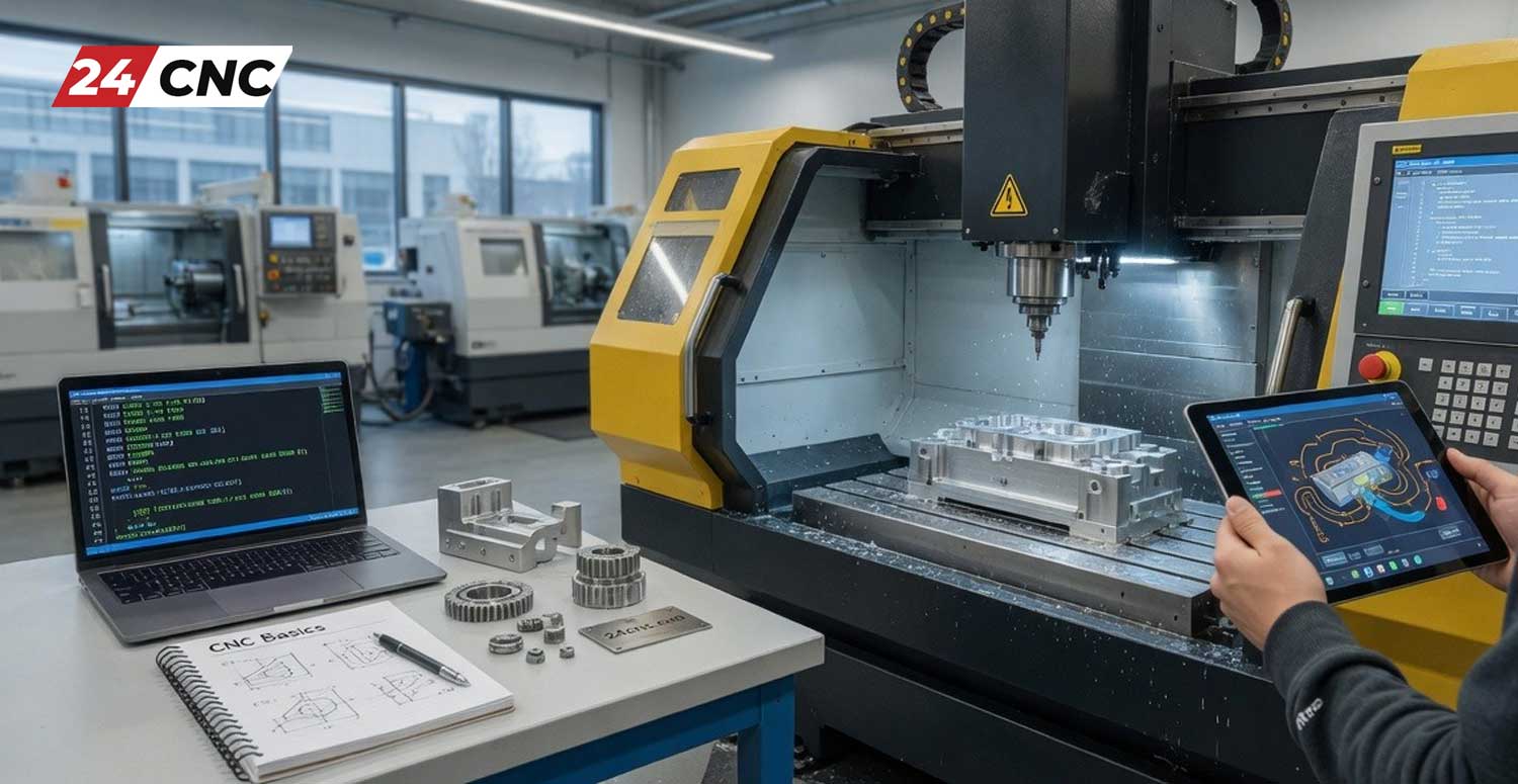
Before you even think about writing a single line of code, you must completely rethink how you view physical space. CNC machines are blind; they do not have eyes to see the raw material. Instead, they rely entirely on a mathematical grid known as the Cartesian Coordinate System. If you remember your high school geometry, you are already halfway there.
In a standard 3-axis CNC vertical milling machine, space is divided into three primary linear axes:
- The X-Axis: This represents the horizontal movement of the machine table (left and right relative to the operator).
- The Y-Axis: This represents the depth movement of the table (forward and backward, moving toward or away from the operator).
- The Z-Axis: This is arguably the most critical axis for safety. It represents the vertical movement of the spindle (the rotating cutting tool) moving up and down. Moving down (Z-negative) cuts into the material, while moving up (Z-positive) retracts the tool to safety.
Modern manufacturing often requires more complex movements, leading to the development of 4-axis and 5-axis machines, which introduce rotational axes (A, B, and C). To dive deeper into how these advanced machines operate, check out our guide on Understanding CNC Machine Axes (3-Axis to 5-Axis).
Machine Zero vs. Work Zero
A crucial concept for beginners to grasp is the difference between zero points. Machine Zero (Home Position) is a fixed point designated by the manufacturer, usually at the extreme positive limits of all axes. However, programming from Machine Zero is a nightmare. Instead, we use Work Zero (Part Zero). This is a custom origin point (X0, Y0, Z0) that the operator sets on the actual raw material (the billet). All your programmed coordinates will be relative to this Work Zero, making the math significantly easier.
The Language of Manufacturing: Decoding G-Code
When we talk about “CNC Programming,” we are primarily talking about G-Code. This is the alphanumeric language that dictates the physical geometry of the toolpath. For a supplementary beginner’s perspective, our post An Introduction to G-Code for Beginners is a great companion piece. Below is a detailed breakdown of the most essential G-Codes every absolute beginner must memorize.
The Primary Motion Codes
- G00 (Rapid Positioning): This tells the machine to move to a specific coordinate as fast as its motors will allow. Crucial rule: Never use G00 when the cutting tool is engaged with the material. It is strictly for moving through the air.
- G01 (Linear Interpolation): This is your primary cutting code. It tells the machine to move in a straight line at a specific, controlled speed (known as the Feed Rate).
- G02 (Circular Interpolation Clockwise): Used for cutting arcs and circles in a clockwise direction. It requires you to specify the center of the arc using I and J coordinates or an R (radius) value.
- G03 (Circular Interpolation Counter-Clockwise): The exact opposite of G02; used for counter-clockwise arcs.
Positioning and Unit Codes
- G20 and G21: G20 sets the machine to read coordinates in Inches (Imperial), while G21 sets it to Millimeters (Metric). Mixing these up will result in catastrophic part failures.
- G90 (Absolute Positioning): The machine reads all coordinates based on the single Work Zero point. If you command X10, the tool goes to the position 10 units away from zero.
- G91 (Incremental Positioning): The machine reads coordinates based on its current position. If the tool is at X5, and you command X10 in G91 mode, it will move an additional 10 units to end up at absolute position X15.
Taking Control with M-Codes and Auxiliary Commands
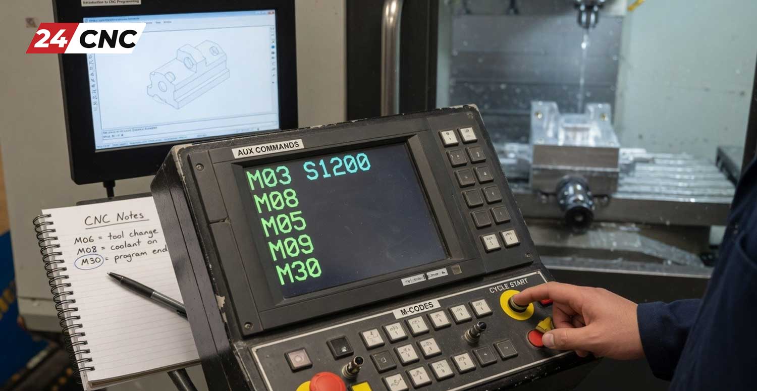
While G-Codes handle the geometry (where the tool goes), M-Codes (Miscellaneous Codes) act as the hardware switches. They turn physical components of the machine on and off. Furthermore, other letters like S, F, and T complete the program. To understand how the machine’s brain processes these, read about What a CNC Controller Interprets.
- M00 (Program Stop): Forces the machine to stop everything and wait for the operator to press the Start button. Useful for mid-operation inspections.
- M03 and M04 (Spindle Control): M03 turns the spindle on in a clockwise (Forward) direction, which is standard for most cutting tools. M04 turns it on counter-clockwise (Reverse), usually used for specialized tapping operations.
- M05 (Spindle Stop): Halts the rotation of the spindle.
- M06 (Tool Change): Commands the machine’s Automatic Tool Changer (ATC) to swap the current tool for a new one.
- M08 and M09 (Coolant Control): M08 turns the flood coolant pump on to lubricate the cut and clear chips. M09 turns the coolant off.
- M30 (End of Program): Signals that the machining process is complete. It stops the spindle, turns off coolant, and rewinds the code back to the very first line for the next part.
Alongside M-Codes, we use S-Codes for Spindle Speed (e.g., S2500 means 2500 Revolutions Per Minute) and F-Codes for Feed Rate (e.g., F500 means the tool will move through the material at 500 millimeters per minute). T-Codes select the tool number (e.g., T01 prepares Tool #1).
The Brain of the Operation: Understanding CNC Controllers
You can write the most perfect G-Code in the world, but without a controller to interpret it, it is just text on a screen. The CNC Controller is an industrial computer wired directly to the machine’s servos, encoders, and relays. While the foundation of G-Code (ISO standard) is universal, different controller brands have unique “dialects,” especially when it comes to complex operations like Canned Cycles (pre-programmed drilling or tapping sequences).
Two of the absolute giants in the industrial world are Fanuc™ and Siemens. Fanuc is incredibly robust, reliable, and holds a massive market share globally. Siemens offers highly advanced, user-friendly conversational programming interfaces on their Sinumerik platforms. If you are building, retrofitting, or repairing a machine, sourcing high-quality control components is vital. You can explore our extensive inventory of Fanuc™ Controller parts or browse our high-end Siemens automation equipment directly in our shop.
Manual Programming vs. Modern CAD/CAM Software
A common question from absolute beginners is: “Do I really have to type thousands of lines of code by hand?” The answer is a resounding no, though understanding how to read those lines remains critical. Today, the industry is split between manual coding for simple tasks and CAD/CAM software for complex geometries. To visualize this modern workflow, review our article on How CNC Parts are Made: From 3D Model to Finished Product.
| Feature / Metric | Manual Programming (By Hand) | CAD/CAM Software Programming |
|---|---|---|
| Ideal Application | Simple 2D profiles, bolt hole circles, facing operations, and quick on-the-fly shop floor edits. | Complex 3D organic shapes, mold making, aerospace components, and simultaneous 5-axis machining. |
| Code Generation Speed | Very slow. Requires the programmer to calculate trigonometry and cutter coordinates manually. | Extremely fast. Software algorithms can generate millions of lines of optimized code in seconds. |
| Risk of Human Error | High. A single misplaced decimal point (e.g., X10 vs X10.0) can cause a catastrophic machine crash. | Low. High-end CAM software includes digital twin simulation to verify toolpaths before actual cutting. |
| Prerequisite Skills | Deep memorization of G & M codes, strong math skills, and intimate knowledge of the controller. | Proficiency in 3D modeling (CAD) and understanding of machining strategies, tooling, and feed/speed formulas. |
Pro-Tip for Beginners: Do not skip straight to CAM software. If you do not understand the raw G-Code, you will not know how to troubleshoot when the CAM software inevitably generates an inefficient or dangerous toolpath. Learn manual coding first; it will make you a vastly superior CAM programmer later.
The Anatomy of a CNC Program Block
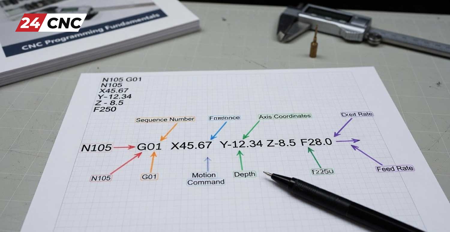
Let’s put everything we’ve learned together. In CNC programming, a single line of code is referred to as a Block. The machine reads these blocks sequentially, one by one, from top to bottom. Here is a breakdown of a very simple, standardized program block sequence:
O1001 (PROGRAM NAME – SIMPLE DRILL)
N10 G90 G21 G17 G40 G80 (Safety Block: Absolute, Metric, XY Plane, Cancel Comp, Cancel Cycles)
N20 T01 M06 (Call Tool Number 1 and execute Tool Change)
N30 S2000 M03 (Turn Spindle ON Clockwise at 2000 RPM)
N40 G00 X25.0 Y25.0 (Rapid move over the first hole location)
N50 G43 H01 Z10.0 M08 (Apply Tool Height Offset 1, rapid to 10mm above part, Coolant ON)
N60 G01 Z-5.0 F150 (Feed down 5mm into the material at 150 mm/min)
N70 G00 Z10.0 (Rapid retract out of the hole to safe clearance)
N80 G91 G28 Z0 M09 (Return to Z Home Position, Coolant OFF)
N90 M30 (End of Program and Rewind)
%
Notice line N50. It contains G43 H01. This is incredibly important. G43 tells the machine to activate Tool Length Compensation. Because every tool (a drill, an endmill, a face mill) has a different physical length, the machine needs to offset the Z-axis by the exact length of that specific tool (stored in the controller’s register under H01). Without G43, the machine would plunge the spindle directly into the table, causing a devastating crash.
Crucial Best Practices & Avoiding Costly Mistakes
In web development, a bad line of code throws an error on a screen. In CNC programming, a bad line of code throws a 5-pound chunk of steel across the room or shatters a $50,000 spindle. Safety and verification are paramount.
- Beware the Decimal Point: On older Fanuc and Haas controllers, omitting a decimal point can be disastrous. If you want to move 10 millimeters, you must write
X10.0. If you writeX10, the controller might read it in internal machine units (microns), moving the machine only 0.01mm. Always double-check your decimals! - Always Run a Simulation: Use the controller’s onboard graphical verification tool to trace the toolpath on the screen before pressing Cycle Start.
- Cut Air First (Dry Run): A “Dry Run” means running the program with the actual raw material removed from the vise, or running the program with the Z-axis offset artificially high. This allows you to watch the physical motions of the machine in real space without risking a tool collision.
- Keep One Hand on the Feed Hold: When running a new, unproven program for the very first time, the operator should have their finger hovering over the Feed Hold (Pause) or Emergency Stop (E-Stop) button, ready to react if the machine moves unexpectedly.
Frequently Asked Questions (FAQ) About CNC Programming
1. Do I need to be a math genius to learn CNC programming?
Absolutely not. While an advanced understanding of trigonometry is helpful for manual programming of complex angles, basic arithmetic and a solid grasp of Cartesian geometry (X, Y, Z coordinates) are entirely sufficient to get started. Modern CAM software handles all the heavy mathematical lifting and complex calculations for you.
2. How long does it realistically take to learn?
You can learn the basic G-Codes and write simple manual programs (like drilling a bolt circle or facing a square block) in just 2 to 4 weeks of dedicated study. However, mastering advanced CAM software, understanding feed and speed metallurgy, and becoming an expert programmer who can optimize cycle times takes years of hands-on, practical experience.
3. What is the best software for an absolute beginner to start with?
If you want to practice raw G-Code safely without a machine, software like CNC Simulator Pro or NC Viewer (browser-based) is excellent. When you are ready to step up to CAD/CAM, Autodesk Fusion 360 is highly recommended for beginners due to its massive community, vast array of free tutorials on YouTube, and integrated CAD-to-CAM workflow. In industrial environments, Mastercam and SolidCAM are industry standards.
4. Will code written for one machine work perfectly on another?
Not always! While the core ISO G-Codes (like G00, G01, M03) are nearly universal across the globe, specific Canned Cycles (like G83 for peck drilling), macro variables, and specialized M-Codes vary dramatically between manufacturers (e.g., Haas vs. Siemens). You must always run your CAM program through a specific Post-Processor designed exactly for your machine’s make and model.
Final Thoughts on Your CNC Journey
Learning CNC programming is like learning to play a musical instrument. You start by learning the individual notes (G-Codes and M-Codes), then you learn how to string them together into simple chords (programming blocks), and eventually, with practice and software tools, you will be conducting entire symphonies of metal removal. Focus intensely on the fundamentals of the Cartesian coordinate system, prioritize safety over speed, and never stop learning. The manufacturing industry is constantly evolving, and a solid foundation in programming will ensure you evolve right alongside it.
Need to Upgrade or Repair Your CNC Equipment?
Whether you are an absolute beginner assembling your first desktop router or an experienced industrial manufacturer maintaining a fleet of 5-axis machining centers, your code is only as good as the hardware executing it. At 24CNC, we stock an exhaustive inventory of premium replacement parts, advanced controllers, servo drives, and precision motors—all guaranteed for authenticity and performance.
Leave a comment
Your email address will not be published. Required fields are marked *