How to Troubleshoot Inaccurate Readings from a Rotary Encoder

How to Troubleshoot Inaccurate Readings from a Rotary Encoder

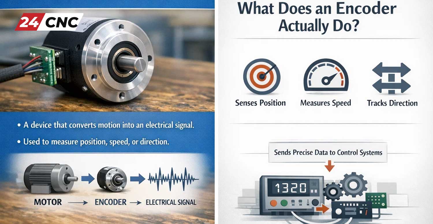
There are few things more frustrating for a CNC operator or robotics engineer than a machine that doesn’t move as commanded. When an axis overshoots its target, jitters erratically, or fails to report its position, the entire system becomes unreliable. In a vast number of cases, the root cause isn’t a complex control board failure but a more fundamental problem: inaccurate readings from a rotary encoder.

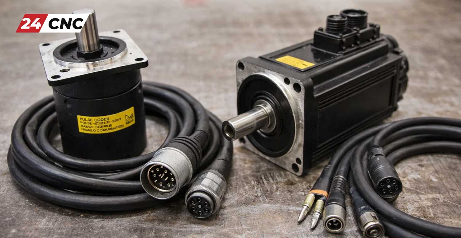
Whether it’s a simple incremental encoder on a DIY project or a high-precision absolute encoder on a Fanuc servo motor, the data it provides is the bedrock of closed-loop motion control. This guide provides a systematic, step-by-step process to diagnose and fix the most common causes of encoder inaccuracy, helping you restore precision and reliability to your equipment.

Understanding the “Why”: Common Types of Encoder Inaccuracy

Before you can fix the problem, you must correctly identify the symptom. Inaccurate readings manifest in several distinct ways:

  • Skipping Counts: The position reading suddenly jumps or fails to update, causing the machine to lose its true position over time. This is common during rapid movements.
  • Jittery or “Noisy” Readings: The position value fluctuates wildly even when the shaft is stationary or moving smoothly.
  • Incorrect Direction: The encoder reports movement in the opposite direction of the actual rotation.
  • No Signal / Total Failure: The controller receives no data from the encoder whatsoever.

By identifying the specific type of failure, you can narrow down the list of potential causes and start your troubleshooting in the most logical place.

How to Troubleshoot Inaccurate Readings from a Rotary Encoder

The Foundation: A Systematic Troubleshooting Checklist

The key to efficient troubleshooting is to start with the simplest and most common failures first before moving on to more complex diagnostics. Follow this methodical approach to avoid wasted time and unnecessary parts replacement.

Step 1: Mechanical & Physical Inspection

Before you even pick up a multimeter, perform a thorough visual and physical inspection. Mechanical issues are surprisingly common and easy to fix.

  • Shaft Coupling: Check the coupling between the motor/spindle shaft and the encoder shaft. Is it tight? A loose setscrew can cause “backlash” where the motor shaft rotates slightly before the encoder shaft begins to move, leading to missed counts.
  • Mounting Stability: Ensure the encoder body is securely mounted and cannot wobble. Excessive machine vibration can translate into the encoder’s internal components, causing reading errors.
  • Cable Integrity: Visually inspect the entire length of the encoder cable. Look for signs of physical damage, crushing, sharp bends, or abrasion that could have compromised the internal wires. Pay close attention to the connection points.
  • Contamination: In industrial environments, are the encoder’s seals intact? The ingress of oil, coolant, or metal dust can destroy the sensitive optics or electronics inside.

Step 2: Electrical & Connection Verification

If the mechanical inspection reveals no issues, the next step is to verify the electrical connections. Faulty wiring is the second most common cause of encoder problems.

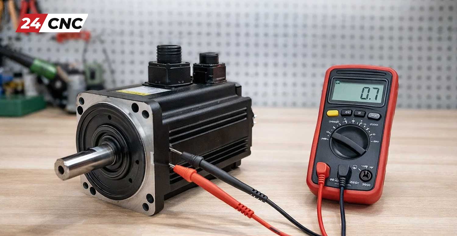
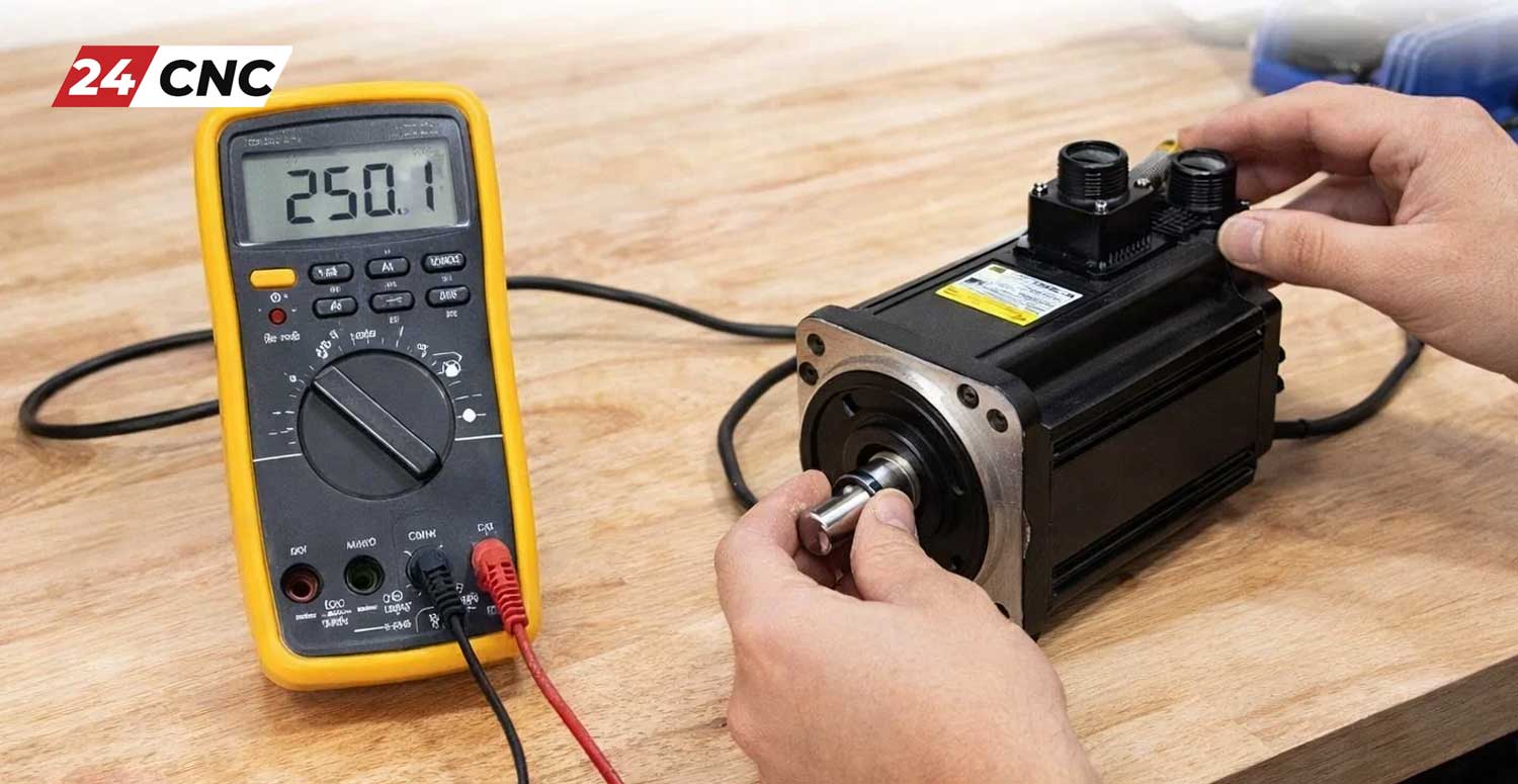
  • Power Supply: Is the encoder receiving the correct voltage (e.g., 5V, 12V, 24V)? Use a multimeter to check the voltage at the encoder’s power pins. A low or fluctuating voltage can cause unpredictable behavior.
  • Loose Wiring: Tug gently on each wire at the controller terminal and at the encoder’s connector. A poorly crimped pin or a loose screw terminal can cause intermittent connections that manifest as jitter or signal loss.
  • Grounding: Poor grounding is a major source of electrical noise. Ensure there is a solid, low-resistance ground path from the encoder body, through the cable shield, to the main system ground. Avoid “ground loops” where a system is grounded at multiple points, creating a potential difference.

How to Troubleshoot Inaccurate Readings from a Rotary Encoder

Advanced Diagnostics for Persistent Encoder Errors

If basic checks don’t solve the problem, it’s time to investigate more complex signal integrity issues. This is where most persistent, hard-to-diagnose problems lie.

The #1 Culprit: Electrical Noise and Signal Integrity

CNC machines are electrically noisy environments. Variable Frequency Drives (VFDs), servo drives, and contactors all generate powerful electromagnetic interference (EMI) and radio-frequency interference (RFI) that can corrupt the low-voltage signals from an encoder.

Solution 1: Proper Cabling & Shielding. Never use unshielded wire for an encoder run. A high-quality, dedicated encoder cable with both a foil wrap and a braided shield is essential. The shield should be connected to ground at the controller end only to prevent ground loops.

Solution 2: Hardware Filtering. For cheaper Manual Pulse Generators (MPGs) or incremental encoders prone to “contact bounce,” a simple RC low-pass filter (e.g., a 1kΩ resistor and a 0.1µF capacitor) on the signal lines can filter out the high-frequency noise of the bounce.

Decoding Errors: Issues with Quadrature Signals

An incremental encoder’s A and B channel signals must maintain a precise 90-degree phase relationship. An oscilloscope is the ultimate tool for verifying this. By probing the A and B channels, you can instantly see issues like:

  • Signal Degradation: Over long cable runs, square waves can become rounded, making it difficult for the controller to read them accurately. This is often solved by using an encoder with a differential line driver (RS-422).
  • Glitches & Noise: You can visually see noise spikes on the signal lines that correspond with another machine component (like a VFD) turning on.
  • Phase Shift: If the A/B phase relationship is incorrect, the controller may read the direction of rotation incorrectly.

Controller & Software-Level Problems

Sometimes the encoder is working perfectly, but the system reading it is at fault.

  • Missed Pulses: If the controller’s main processor is too busy, it might miss pulses from the encoder, especially during high-speed rotation. This is why industrial controllers use dedicated hardware counters or interrupt-driven routines.
  • Configuration Errors: A modern control system must be configured correctly. Check if the controller’s parameters match the encoder’s Pulses Per Revolution (PPR) and signal type (single-ended vs. differential). A mismatch here will result in incorrect distance calculations.

Troubleshooting Methods: A Comparative Overview

The right approach can differ based on the encoder’s technology and the symptom observed.

Problem Common Cause DIY / Mechanical Encoder Fix Industrial Optical Encoder Fix
Jittery Reading Contact Bounce / EMI Add RC filter; improve software debouncing. Check shield grounding; separate cable from motor wires.
Skipping Counts Slow Polling / Slippage Switch to interrupt-based code; tighten shaft coupling. Check controller PPR settings; verify line driver integrity.
Wrong Direction Swapped A/B Wires Swap the A (CLK) and B (DT) wires at the controller. Swap the A and A- (or B and B-) wires at the controller.
No Signal Power Loss / Broken Wire Check VCC/GND with a multimeter; check for wire breaks. Check power supply; check for controller alarm codes; replace cable.

How to Troubleshoot Inaccurate Readings from a Rotary Encoder

When to Repair vs. Replace: Making the Call

The decision to repair or replace an encoder is largely economic. For a low-cost hobbyist encoder, replacement is almost always the best option. However, for a high-performance industrial encoder, troubleshooting is crucial. A genuine Fanuc encoder or Mitsubishi encoder can cost hundreds or thousands of dollars. In these cases, correctly identifying a fixable issue like a bad cable or a faulty power supply can save significant time and money compared to ordering a replacement part.

Frequently Asked Questions (FAQ)

How can I test an encoder without an oscilloscope?

While an oscilloscope is best, you can perform basic tests. With the encoder powered, use a multimeter set to DC volts. Connect the negative probe to ground and the positive probe to Channel A. As you slowly rotate the encoder shaft, you should see the voltage pulse between low (near 0V) and high (near VCC). Repeat for Channel B. If the voltage doesn’t change or stays intermediate, the channel is likely faulty.

What is an “alarm code” related to an encoder?

Professional CNC systems like a Fanuc controller have advanced diagnostics. If they detect a loss of signal, an incorrect pulse count, or other encoder-related error, they will stop the machine and display a specific alarm code (e.g., “SV0433 – DC Link voltage is abnormally high” or “SV0401 – SERVO ALARM: L AXIS VRDY OFF”). This code is the most important starting point for troubleshooting on industrial machinery, as it points you directly to the axis and nature of the fault.

Does the length of the encoder cable really matter?

Absolutely. The longer the cable, the higher its capacitance and resistance, which can degrade the signal. More importantly, a longer cable acts as a larger antenna, making it much more susceptible to picking up ambient electrical noise from motors and drives. For runs longer than a few meters, it is critical to use encoders with differential line driver outputs (RS-422) and high-quality, properly shielded cables.

What’s the difference between single-ended and differential encoder signals?

A single-ended signal (common in hobby electronics) uses one wire per channel plus a ground. A differential signal uses two wires per channel (e.g., A and A-). The controller looks at the voltage difference between the two wires, not their voltage relative to ground. Since noise tends to affect both wires equally, it gets cancelled out, providing vastly superior noise immunity. This is the standard for all reliable industrial motion control.

Conclusion

Troubleshooting inaccurate encoder readings requires a methodical approach that moves from the simple to the complex: check the mechanics, verify the electrics, analyze the signal, and finally, question the software. By systematically eliminating potential causes, you can efficiently pinpoint the source of the problem. Patience and a logical process will almost always reveal the fault, whether it’s a loose screw or a complex noise issue, allowing you to get your machinery back to running with the precision you depend on.

Encoder Still Giving You Trouble?

Don’t let a faulty encoder stop your production. We stock a huge range of genuine replacement encoders, high-quality cables, and control system components for all major brands. Get the right part, fast.

Shop Replacement Encoders Now

A Guide to Wiring a Rotary Encoder to Arduino and ESP32 for DIY Projects

A Guide to Wiring a Rotary Encoder to Arduino and ESP32 for DIY Projects

Whether you are building a custom menu interface, a robotics project, or designing your own DIY CNC machine, mastering the rotary encoder is a critical skill. Unlike standard potentiometers that have a limited range of motion, rotary encoders can rotate infinitely, providing precise digital feedback regarding position, speed, and direction. This makes them indispensable in modern electronics.

In this comprehensive guide, we will walk you through everything you need to know about wiring, programming, and troubleshooting a rotary encoder using the two most popular microcontrollers in the maker community: the Arduino and the ESP32. We will also explore how these DIY concepts scale up to industrial applications, such as CNC handwheels and automated control systems.

Understanding the Basics: How Does a Rotary Encoder Work?

Before diving into wires and code, it is essential to understand the mechanics behind the hardware. A rotary encoder is an electro-mechanical device that converts the angular position or motion of a shaft into analog or digital output signals.

There are two main types of rotary encoders:

  • Absolute Encoders: These output a unique digital code for every distinct angle of the shaft. They “remember” their position even after a power cycle.
  • Incremental Encoders: These generate a series of pulses as the shaft rotates. They do not know their absolute position upon startup; they only track how far they have moved from a given starting point. This is the most common type used in DIY projects (such as the popular KY-040 module).

The Quadrature Output Explained

Incremental encoders typically utilize a “quadrature” output. Inside the encoder, a slotted disc rotates between light sensors (or mechanical contacts in cheaper models), generating two separate square wave signals, commonly referred to as Channel A (CLK) and Channel B (DT).

These two signals are out of phase by 90 degrees. By analyzing which channel transitions first, the microcontroller can determine the direction of rotation (clockwise or counter-clockwise). By counting the number of pulses, it can determine the distance or angle traveled.

A Guide to Wiring a Rotary Encoder to Arduino and ESP32 for DIY Projects

Essential Components for Your Setup

To follow along with this guide, you will need a few basic components:

  • An Arduino board (e.g., Arduino UNO, Nano) or an ESP32 development board.
  • A Rotary Encoder module (the KY-040 is highly recommended for beginners as it includes built-in pull-up resistors).
  • Jumper wires.
  • A breadboard.
  • Optional but recommended: Capacitors ($0.1\mu F$) and resistors ($10k\Omega$) for hardware debouncing, and a high-quality encoder cable to prevent signal noise if placing the encoder far from the board.

Wiring a Rotary Encoder to an Arduino

The Arduino UNO is an excellent starting point for reading encoder signals. While you can read the signals using standard digital polling, using Interrupts is highly recommended to ensure you never miss a pulse, even if the Arduino is busy processing other code.

Arduino Pinout and Connection Diagram

Assuming you are using a standard KY-040 rotary encoder module, the wiring to the Arduino is as follows:

  • GND: Connect to Arduino GND.
  • + (VCC): Connect to Arduino 5V.
  • SW (Switch): Connect to Digital Pin 4 (This is the push-button feature of the encoder).
  • DT (Data / Channel B): Connect to Digital Pin 3.
  • CLK (Clock / Channel A): Connect to Digital Pin 2.

Note: Pins 2 and 3 on the Arduino UNO support hardware interrupts, which is why we route the DT and CLK signals to them.

Example Arduino Code (Using Interrupts)

Here is a robust code snippet that uses hardware interrupts to track the encoder’s position accurately:

#define CLK_PIN 2
#define DT_PIN 3
#define SW_PIN 4

volatile int encoderPosition = 0;
int lastPosition = 0;

void setup() {
Serial.begin(9600);
pinMode(CLK_PIN, INPUT_PULLUP);
pinMode(DT_PIN, INPUT_PULLUP);
pinMode(SW_PIN, INPUT_PULLUP);

// Attach interrupt to the CLK pin
attachInterrupt(digitalPinToInterrupt(CLK_PIN), updateEncoder, CHANGE);
}

void loop() {
if (encoderPosition != lastPosition) {
Serial.print(“Position: “);
Serial.println(encoderPosition);
lastPosition = encoderPosition;
}

if (digitalRead(SW_PIN) == LOW) {
Serial.println(“Button Pressed!”);
delay(200); // Simple debounce
}
}

void updateEncoder() {
int dtValue = digitalRead(DT_PIN);
int clkValue = digitalRead(CLK_PIN);

if (clkValue == dtValue) {
encoderPosition++;
} else {
encoderPosition–;
}
}

Wiring a Rotary Encoder to an ESP32

The ESP32 is significantly more powerful than the standard Arduino UNO. It operates on a 3.3V logic level, meaning you must power your encoder with 3.3V, NOT 5V, to avoid damaging the GPIO pins.

ESP32 Pinout and Connection Diagram

  • GND: Connect to ESP32 GND.
  • + (VCC): Connect to ESP32 3.3V.
  • SW (Switch): Connect to GPIO 25.
  • DT (Data / Channel B): Connect to GPIO 26.
  • CLK (Clock / Channel A): Connect to GPIO 27.

Note: Almost all GPIO pins on the ESP32 support interrupts, giving you much more flexibility in your wiring layout.

Example ESP32 Code

While you can use the exact same interrupt logic as the Arduino, the ESP32 is fast enough to handle standard hardware interrupts seamlessly. Here is the adapted code for the ESP32:

#define CLK_PIN 27
#define DT_PIN 26
#define SW_PIN 25

volatile int encoderCounter = 0;
int lastCounter = 0;
portMUX_TYPE mux = portMUX_INITIALIZER_UNLOCKED;

void IRAM_ATTR isr() {
portENTER_CRITICAL_ISR(&mux);
int dtVal = digitalRead(DT_PIN);
int clkVal = digitalRead(CLK_PIN);

if (clkVal == dtVal) {
encoderCounter++;
} else {
encoderCounter–;
}
portEXIT_CRITICAL_ISR(&mux);
}

void setup() {
Serial.begin(115200);
pinMode(CLK_PIN, INPUT_PULLUP);
pinMode(DT_PIN, INPUT_PULLUP);
pinMode(SW_PIN, INPUT_PULLUP);

attachInterrupt(digitalPinToInterrupt(CLK_PIN), isr, CHANGE);
}

void loop() {
if (encoderCounter != lastCounter) {
Serial.print(“ESP32 Encoder Position: “);
Serial.println(encoderCounter);
lastCounter = encoderCounter;
}
}


The Critical Importance of Debouncing

Mechanical rotary encoders suffer from a phenomenon known as “contact bounce.” When the metal contacts inside the encoder touch and separate, they can bounce on a microscopic level, creating multiple false signals in a fraction of a millisecond. If left untreated, your microcontroller will count these bounces as actual rotations, leading to wild and erratic readings.

Software Debouncing

Software debouncing involves ignoring any signals that occur within a few milliseconds of each other. While the `delay()` function works for basic buttons, it ruins the fast responsiveness required for encoders. Instead, timing functions like `millis()` should be used to filter out noise.

Hardware Debouncing (RC Filter)

The most reliable method is implementing a hardware RC (Resistor-Capacitor) low-pass filter on the CLK and DT lines. By adding a $10k\Omega$ resistor in series and a $0.1\mu F$ capacitor to ground, you smooth out the erratic voltage spikes.

The cutoff frequency for this RC filter can be calculated using the formula:

$$f_c = \frac{1}{2 \pi R C}$$

With a $10k\Omega$ resistor and a $0.1\mu F$ capacitor, the cutoff frequency is approximately $159 Hz$, effectively filtering out the high-frequency mechanical bounce while allowing human-speed rotations to pass through perfectly.

A Guide to Wiring a Rotary Encoder to Arduino and ESP32 for DIY Projects

Applications: From Simple DIY to Industrial CNC Handwheels

Once you understand how to interface a basic KY-040 encoder with a microcontroller, a massive world of applications opens up. In simple DIY electronics, encoders are used for volume knobs, menu navigation screens, and robotic wheel odometry.

However, the exact same underlying principles apply to industrial manufacturing and CNC machining. In the professional realm, rotary encoders are scaled up into heavy-duty Manual Pulse Generators (MPGs) or handwheels. These industrial handwheels allow machinists to manually position heavy CNC axes with micrometer precision.

While a DIY Arduino project uses a $2 encoder, an industrial control system might rely on a high-precision Fanuc encoder that outputs thousands of pulses per revolution (PPR) via differential signals (RS422) for extreme noise immunity over long cable runs. Despite the difference in scale and price, the core concept of counting quadrature pulses remains identically rooted in the logic you just learned.

Technical Comparison: Arduino vs. ESP32 for Encoder Interfacing

Which microcontroller is best for your encoder project? Review this technical breakdown to decide.

Feature Arduino UNO ESP32
Operating Voltage 5V Logic 3.3V Logic
Hardware Interrupt Pins Only Pins 2 & 3 Almost all GPIOs
Clock Speed 16 MHz 160 – 240 MHz
Hardware Pulse Counter (PCNT) No Yes (Dedicated hardware subsystem)
Best Use Case Simple menus, basic DIY robotic feedback. High-speed rotational tracking, complex CNC interfaces, IoT remote monitoring.

Frequently Asked Questions (FAQ)

Why is my rotary encoder skipping values or counting backwards?

This is almost always caused by mechanical switch bounce. When you rotate the encoder, the internal contacts bounce, creating false signals. You must implement either software debouncing using a timing variable or, ideally, hardware debouncing using a small capacitor and resistor on the output pins.

Can I use a 5V encoder on the ESP32?

The ESP32 has a strictly 3.3V logic level limit. Connecting a 5V signal directly to an ESP32 GPIO pin can permanently damage the board. You must either power the encoder with 3.3V (most KY-040 modules work fine at 3.3V) or use a logic level converter.

How do I read a high-resolution industrial encoder with an Arduino?

High-resolution encoders output pulses much faster than a standard Arduino can read via basic interrupts. For industrial encoders (e.g., 2000+ PPR), you will need dedicated quadrature decoder ICs (like the LS7366R) or a much faster microcontroller like an ESP32 utilizing its dedicated PCNT (Pulse Counter) hardware peripheral.

Conclusion

Wiring and programming a rotary encoder with an Arduino or ESP32 is a fantastic way to introduce precise control and feedback into your DIY projects. By understanding quadrature signals, utilizing hardware interrupts, and effectively debouncing the output, you can create smooth, professional-feeling interfaces.

The skills you learn manipulating simple DIY encoders are highly transferable. The logic remains exactly the same whether you are turning down the volume on a custom Bluetooth speaker or dialing in the Z-axis on a massive industrial CNC milling machine.

Ready to Upgrade Your CNC Projects?

Whether you are transitioning from Arduino prototypes to professional builds, or repairing high-end industrial machinery, precision is everything. Explore our extensive catalog of genuine, high-performance CNC electronics and rotary encoders.

Shop Industrial Rotary Encoders Today

Replace a Faulty Encoder

How to Replace a Faulty Encoder on a Fanuc Servo Motor

In the high-stakes environment of CNC machining, a faulty servo motor encoder can bring production to a grinding halt. The encoder, often referred to by Fanuc as a “Pulse Coder,” is the eyes of your machine’s control system. It tells the Fanuc controller exactly where the motor is, how fast it’s spinning, and in which direction. When this feedback loop breaks, accuracy vanishes, and alarms trigger.

Replacing a Fanuc encoder is a precise task, but it is manageable with the right knowledge. Unlike a simple mechanical part swap, this procedure involves delicate electronics and critical calibration steps to ensure your machine returns to its correct home position. This guide will walk you through diagnosing the issue, physically replacing the unit, and the essential steps required to get your machine back up and running.

Replace a Faulty Encoder

Step 1: Diagnosing the Fault – Is It Really the Encoder?

Before you order a replacement Fanuc encoder, you must confirm that the component is indeed the source of the problem. Often, cable issues or drive faults can mimic encoder failures.

Common Fanuc Encoder Alarms

Fanuc systems communicate errors via specific alarm codes on the CNC monitor. Look for these common indicators:

  • Alarm 300, 310, 320: Request for reference position return. This often happens if the absolute position data is lost (often a dead battery), but can indicate encoder failure if the battery is good.
  • Alarm 360, 361, 364, 368: Pulse coder invalid, phase data errors, or communication errors. These point directly to the encoder or the communication line.
  • Alarm 369: Data transfer error.

The “Cable Check” Rule

Before condemning the encoder, inspect the encoder feedback cable. Oil ingress, coolant contamination, or a pinched wire in the drag chain can cause communication errors that look exactly like a hardware failure. Clean the connectors on both the motor side and the drive side before proceeding.

Step 2: Preparation and Safety

Working on servo motors involves electrical hazards and potential mechanical movement. Follow these safety protocols:

  1. Power Down: Turn off the main breaker to the CNC machine. Lockout/Tagout procedures should be followed.
  2. Secure the Axis: If you are working on a vertical axis (Z-axis) or a slanted axis, mechanically block or prop the axis to prevent it from dropping when the motor or brake is disengaged.
  3. Gather Tools: You will typically need a set of metric Allen keys (hex wrenches), a Phillips screwdriver, a clean rag, and potentially a specialized puller if the coupling is tight.
  4. Identify the Part: Check the label on your motor and existing encoder. Fanuc encoders come in Alpha ($\alpha$), Beta ($\beta$), and Serial variations. Ensure your replacement matches exactly.

Replace a Faulty Encoder

Step 3: Removing the Faulty Pulse Coder

Once the machine is safe and accessible, proceed with the removal.

1. Access the Encoder

Remove the red or yellow plastic cover on the back of the Fanuc servo motor. This is usually held on by snap-fits or small screws. You will see the metal body of the Pulse Coder underneath.

2. Disconnect the Cable

Carefully unplug the feedback cable. For many Fanuc motors, this is a distinct connector (Canon plug or MS connector). Inspect the pins for corrosion or coolant. If the connector is damaged, you may need to repair the socket and connector as well.

3. Remove the Mounting Screws

The encoder is typically secured to the motor shaft housing by 3 or 4 hex screws. Loosen these screws evenly. Do not attempt to pry the encoder off with a screwdriver, as you may damage the mating surface on the motor.

4. Extract the Encoder

Gently pull the encoder straight back. It connects to the motor shaft via an Oldham coupling or a cross-slotted shaft. It should slide off with minimal resistance. If it sticks, check for a central locking screw (common on some older models) hidden under a cap in the center of the encoder.

Step 4: Installing the New Fanuc Encoder

Cleanliness is paramount here. A single chip of metal or a drop of coolant inside the encoder housing can destroy the new unit.

1. Inspect the Coupling

Check the coupling on the motor shaft. It should be intact and clean. If the old coupling is worn or plastic fragments are visible, replace the coupling before installing the new encoder.

2. Check the O-Ring

Most Fanuc Pulse Coders have an O-ring to seal against the motor housing. Ensure the new unit has this O-ring and apply a very light film of grease to it to ensure a waterproof seal.

3. Align and Seat

Align the shaft of the encoder with the motor shaft coupling. Gently push the encoder onto the motor. It should seat flush against the motor housing without force. If there is a gap, the coupling is not aligned—pull it back and try again. Never force it with the screws.

4. Secure and Reconnect

Tighten the mounting screws in a star pattern to ensure even pressure. Reconnect the feedback cable, ensuring the connector “clicks” or screws on tightly to seal out moisture. Replace the external plastic motor cover.

Replace a Faulty Encoder

Step 5: The Critical Reset (Zero Return Mastering)

This is the step most beginners overlook. Because you have physically removed the feedback device, the CNC control system has lost the relationship between the motor’s position and the machine’s physical “home.”

If you have an Absolute Pulse Coder (which most modern Fanuc motors use), you will likely see an “APC” (Absolute Pulse Coder) alarm requiring a zero return. You cannot simply press the “Home” button because the machine doesn’t know where it is.

General Procedure for Reference Point Reset (Dogless/APC):

  1. Parameter Write Enable: Go to MDI mode, press the OFFSET/SETTING key, find “Parameter Write,” and set it to 1 (Enable).
  2. Navigate to System Parameters: Press SYSTEM and search for parameter 1815.
  3. Adjust Bit 4 (APZ): Locate the axis you worked on (X, Y, or Z). Under parameter 1815, look for bit 4 (APZ). Change this from 1 to 0. This tells the controller “I don’t know where home is.”
  4. Cycle Power: Turn the CNC off and back on.
  5. Jog to Home: Manually jog the axis to the physical location you want to be “Home” (usually aligning match marks on the machine way covers).
  6. Set APZ to 1: Go back to parameter 1815 and set bit 4 (APZ) back to 1.
  7. Cycle Power: Restart the machine. The position should now be memorized.

Note: The specific parameters may vary slightly depending on your controller generation (e.g., 0i-MD vs. 31i-B). Always consult your machine tool builder’s manual.

Technical Comparison: Fanuc Pulse Coder Types

Understanding which encoder you are replacing is vital. Mixing types will result in immediate system errors.

Feature Incremental Encoder ($\alpha I, \beta I$) Absolute Encoder ($\alpha A, \beta A$)
Position Retention Loses position when power is off. Requires “homing” every startup. Remembers position via battery backup even when power is off.
Battery Requirement No battery required. Requires 6V battery backup (located in the Fanuc drive or battery box).
Replacement Complexity Easier. Usually just requires dog-referencing after install. Higher. Requires full zero-point parameter resetting (APZ).
Common Applications Older machines, spindles, simple conveyors. Modern CNC axes, robotics, high-speed machining centers.

Frequently Asked Questions (FAQ)

Can I repair a Fanuc encoder instead of replacing it?
Generally, no. Fanuc Pulse Coders are sealed, precision optical or magnetic devices. Opening them usually introduces dust that ruins the optics or disturbs the delicate alignment of the internal disk. Replacement is the industry standard for reliability.

I replaced the encoder, but I still have an alarm. What now?
If the alarm persists, check the cable continuity. Old cables can break internally during the maintenance process. Also, ensure the new encoder is compatible with your specific servo amplifier. Finally, verify the 5V power supply from the drive to the encoder is stable.

Why do I need to change batteries if I replace the encoder?
The batteries that maintain the absolute position are often not inside the encoder itself but in the servo amplifier. However, when you unplug the encoder, the circuit is broken, and position data is lost immediately. Always check your backup batteries during this service interval.

Can I upgrade from an Incremental to an Absolute encoder?
This is not a plug-and-play upgrade. It requires changing parameters in the CNC controller, adding battery backup hardware, and often changing the motor or drive configuration. Consult a Fanuc retrofit specialist.

Find the Exact Fanuc Pulse Coder You Need

Don’t risk machine accuracy with used or mismatched parts. Browse our extensive inventory of genuine Fanuc encoders, cables, and servo motors to get your CNC back in production today.

Shop Fanuc Encoders Now

Rotary Encoder PPR Explained

Rotary Encoder PPR Explained: Why Resolution Matters for CNC Precision

In the world of CNC machining, precision isn’t just a goal; it’s a fundamental requirement. The ability to execute a toolpath with microscopic accuracy is what separates a high-quality part from scrap. At the heart of this precision lies a critical component: the rotary encoder. And within the specifications of any encoder, one value stands out as paramount for performance: PPR, or Pulses Per Revolution. But what exactly is PPR, and why is it so crucial for your machine’s accuracy?

This comprehensive guide will demystify PPR, explaining its direct relationship to resolution and how it impacts every aspect of your CNC machine’s performance, from the smoothness of a finished surface to the reliability of a threaded hole. Understanding this concept is key to diagnosing issues, upgrading components, and ultimately, maximizing your machine’s potential.

Rotary Encoder PPR Explained

What is a Rotary Encoder? The Backbone of CNC Motion Control

Before diving into PPR, it’s essential to understand the role of the rotary encoder itself. Think of it as a highly sensitive translator. A rotary encoder is an electro-mechanical device that converts the angular position or motion of a shaft into an electrical signal. In a CNC machine, these are typically attached to servo motors and spindle motors.

As the motor shaft turns, the encoder sends a stream of electrical pulses back to the CNC control system. The controller counts these pulses to determine exactly how far the shaft has rotated and at what speed. This closed-loop feedback system allows the controller to verify that its commands are being executed perfectly. If the controller tells an axis to move 10.005mm, it uses feedback from the encoder to ensure it moves precisely that distance and no more. For a deeper technical dive, you can explore how a rotary encoder works in our detailed guide.

Decoding PPR: What Are Pulses Per Revolution?

PPR (Pulses Per Revolution) is the specification that defines the resolution of an incremental rotary encoder. It tells you how many distinct electrical pulses the encoder will output for one complete 360-degree rotation of its shaft.

Imagine a pizza sliced into 8 pieces. Each slice represents a segment. If you were to count each time you moved from one slice to the next, you would count 8 times for a full circle. In this analogy, the encoder has a resolution of 8 PPR.

Now, imagine a pizza sliced into 2,500 incredibly thin slices. The number of pulses for a full rotation is now 2,500. This is a 2,500 PPR encoder. It can detect much smaller rotational movements than the 8 PPR encoder. Common PPR values for CNC applications range from a few hundred to several thousand, such as 1000, 2500, 4096, or even higher for ultra-precision tasks.

PPR vs. Resolution: The Critical Link to Precision

PPR is the direct measure of an encoder’s resolution. Higher PPR means higher resolution. This is because a higher number of pulses per turn allows the CNC controller to “see” smaller increments of movement.

  • A 1000 PPR encoder divides a single 360° rotation into 1000 pulses. Each pulse represents a rotation of $360 / 1000 = 0.36$ degrees.
  • A 4096 PPR encoder divides the same rotation into 4096 pulses. Each pulse represents a rotation of just $360 / 4096 \approx 0.088$ degrees.

This increased resolution is further enhanced by a technique called quadrature encoding. Most incremental encoders have two output channels, A and B, which are 90 degrees out of phase. The CNC controller can read the rising and falling edges of both signals, effectively multiplying the PPR by four. This resulting value is often called CPR (Counts Per Revolution).

Formula: $CPR = PPR \times 4$

So, a 2500 PPR encoder operating in quadrature mode will provide the controller with $2500 \times 4 = 10,000$ counts per revolution. This is the true resolution the control system works with, enabling it to make incredibly fine adjustments to the motor’s position.

Rotary Encoder PPR Explained

How PPR Directly Impacts CNC Machining Performance

The resolution of your encoders has a direct and tangible effect on the quality and accuracy of your work. Here’s how it breaks down.

Accuracy and Repeatability

Higher PPR leads to better positional accuracy. When the controller can detect smaller movements, it can more precisely position the tool head. This is critical for applications with tight tolerances, such as mold making or aerospace components. It also improves repeatability—the ability to return to the exact same point time and time again, which is vital for mass production.

Surface Finish Quality

When machining curved surfaces or complex contours, the CNC controller executes thousands of tiny linear movements to approximate the curve. With a low-resolution encoder, these tiny movements are larger and “coarser,” which can result in a visibly faceted or rough surface. A high-PPR encoder allows for smaller, smoother micro-movements, resulting in a superior surface finish that requires less secondary processing.

Velocity and Feed Rate Control

A stable and accurate velocity is crucial for consistent tool engagement and chip load. High-PPR encoders provide the controller with more frequent position updates. This data-rich feedback loop allows the servo drive and controller, such as those from leading brands like FANUC or Siemens, to maintain a much smoother and more constant motor speed, especially at very low feed rates. This prevents jittering and ensures consistent cutting quality.

Choosing the Right PPR: A Balancing Act for Optimal Performance

While it might seem like “more is always better,” selecting the highest possible PPR isn’t always the right strategy. The ideal resolution is a balance between the application’s requirements, the controller’s capabilities, and the overall system cost.

Applications Requiring High PPR (2500+)

  • High-Precision Milling and Grinding: For creating complex 3D surfaces, molds, and parts with tolerances in the single-digit micron range.
  • 5-Axis Machining: The complex, simultaneous movements of rotary axes demand extremely fine resolution to maintain tool point accuracy.
  • Direct Drive Spindles: Used for rigid tapping and spindle orientation where precise angular position is non-negotiable.

Applications Where Lower PPR is Sufficient (100-1000)

  • General-Purpose Routers: For wood or plastic cutting where tolerances are more forgiving.
  • Simple Positioning Tasks: Systems designed for simple point-to-point movement rather than complex contouring.
  • Manual Pulse Generators (MPGs): The handwheels used by operators to manually jog axes typically use low-PPR encoders (e.g., 100 PPR) for manageable control.

The Pitfalls of “Too Much” Resolution

Overspecifying an encoder can lead to problems. An extremely high-PPR encoder generates pulses at a very high frequency, especially at high RPMs. This requires a powerful CNC controller that can process this flood of data without missing counts. Additionally, high-frequency signals are more susceptible to electrical noise, which can be introduced by long or poorly shielded encoder cables, potentially causing positioning errors.

Technical Comparison: High PPR vs. Low PPR Encoders

Feature Low PPR Encoder (e.g., 100-500) High PPR Encoder (e.g., 2500+)
Best-Fit Applications Manual Pulse Generators (MPGs), simple positioning, low-speed conveyors. CNC servo motors, precision robotics, high-speed printing, 5-axis machining.
Precision / Resolution Lower. Suitable for applications with wider tolerances. Higher. Capable of detecting minute movements for tight tolerance work.
Max Speed Capability Can typically operate at higher RPMs without overwhelming the controller. The maximum RPM is limited by the controller’s ability to process the high-frequency pulse train.
Signal Integrity More robust and less susceptible to electrical noise due to lower signal frequency. More sensitive to electrical noise. Requires proper shielding and high-quality cables.
Cost Generally less expensive. Generally more expensive due to the precision-engineered internal components.
Controller Processing Demand Low. Can be handled by almost any standard CNC controller. High. Requires a modern, high-speed controller to avoid missed pulses.

Rotary Encoder PPR Explained

PPR in Action: Key CNC Components

The choice of PPR is critical across several components within a CNC machine’s motion control architecture.

Servo and Stepper Motors

This is the most common application. The encoder on a Mitsubishi or FANUC servo motor provides the primary positional feedback for all axis movements. A PPR of 2500 to 10000 (often specified as the post-quadrature CPR) is standard for achieving the precision required in modern machining centers.

Spindle Motors and Threading

For operations like rigid tapping, the CNC controller must perfectly synchronize the Z-axis feed rate with the spindle’s rotation. A high-resolution spindle encoder is essential for this. It allows the controller to track the spindle’s exact angular position, ensuring a perfect thread is cut on every pass.

Frequently Asked Questions (FAQ) about Rotary Encoder PPR

What’s the difference between PPR and CPR?
PPR (Pulses Per Revolution) refers to the number of physical pulses generated by the encoder’s A or B channel during one 360° turn. CPR (Counts Per Revolution) is the total number of countable position changes the controller can decode using quadrature, which reads the rising and falling edges of both channels. For most encoders, CPR = PPR x 4.

Does higher PPR always mean better accuracy?
Not necessarily. While higher PPR provides higher resolution, the machine’s overall accuracy also depends on mechanical factors like backlash, ball screw precision, and structural rigidity. A high-PPR encoder on a mechanically loose machine will not improve final part accuracy. It’s a balance; the encoder’s resolution must be matched by the machine’s mechanical quality.

How do I calculate the linear resolution of my CNC axis from encoder PPR?
You need to know your ball screw’s pitch (the distance it travels per revolution, e.g., 5mm/rev). The formula is:
Linear Resolution = Ball Screw Pitch / (PPR x 4)
For a 2500 PPR encoder on a 5mm pitch ball screw: 5 mm / (2500 x 4) = 5 / 10000 = 0.0005 mm, or 0.5 microns.

What is a good starting PPR for a general-purpose CNC router?
For a hobbyist or general-purpose CNC router used for wood, plastics, and aluminum, an encoder with a resolution between 1000 and 2500 PPR is typically an excellent balance of performance, cost, and compatibility with most controllers.

Can my CNC controller handle a high-PPR encoder?
You must check your controller’s specifications for its maximum encoder input frequency (usually measured in kHz or MHz). This frequency depends on the motor RPM and the encoder’s CPR. Exceeding this limit will result in lost counts and catastrophic positioning errors. Modern controllers from brands like Siemens are generally well-equipped to handle high-frequency inputs.

Need the Right Encoder for Your CNC?

Don’t let the wrong resolution compromise your machine’s performance. Our experts at 24CNC can help you select the perfect rotary encoder for your specific application, from FANUC and Siemens to Mitsubishi models.

Browse Our Rotary Encoders

How a Rotary Encoder Works

How a Rotary Encoder Works: The Ultimate Technical Guide for 2026

In the intricate ballet of industrial automation, precision is everything. Whether it is a robotic arm assembling a microchip or a heavy-duty CNC lathe carving aerospace components, the machine needs to know the exact position of its moving parts at all times. The unsung hero responsible for this critical data is the rotary encoder.

As we move through 2026, encoder technology has evolved, becoming more robust, precise, and integrated than ever before. Yet, the fundamental question remains for many engineers, students, and maintenance professionals: How does a rotary encoder actually work?

This guide serves as a comprehensive resource, dissecting the electromechanical principles behind these devices, comparing the different technologies (Optical, Magnetic, Capacitive), and explaining the critical difference between incremental and absolute feedback. If you are looking to troubleshoot a Fanuc encoder or select a replacement for a custom build, you are in the right place.

What is a Rotary Encoder?

At its core, a rotary encoder (often called a shaft encoder) is an electro-mechanical device that converts the angular position or motion of a shaft or axle into an analog or digital signal. Think of it as a translator.

The motor speaks in “torque and rotation,” while the control system (PLC or CNC controller) speaks in “binary code and pulses.” The encoder bridges this gap, providing the controller with three critical pieces of information:

  • Position: The specific angle of the shaft.
  • Speed: How fast the shaft is turning (Velocity).
  • Direction: Clockwise or Counter-Clockwise rotation.

How a Rotary Encoder Works

The Physics of Detection: Optical vs. Magnetic vs. Capacitive

While the output function is the same, the internal method of detection varies. In 2026, the two most dominant technologies in the CNC world are Optical and Magnetic.

1. Optical Encoders: The Standard for Precision

Optical encoders are the industry standard for high-precision applications. If you open up a high-end Fanuc servo motor, you are likely to find an optical system.

How it works:
The heart of an optical encoder is a glass or plastic disc mounted to the shaft. This disc is chemically etched with thousands of microscopic transparent and opaque lines (like the bars on a jail cell).

A light source (LED) sits on one side of the disc, and a photodetector sits on the other. As the disc spins, the opaque lines block the light, and the transparent lines let it through. The photodetector sees this as a rapid flickering of light, which it converts into electrical pulses.

  • Pros: Extremely high resolution and accuracy.
  • Cons: Susceptible to dust, oil, and vibration (glass discs can shatter).

2. Magnetic Encoders: The Rugged Alternative

Magnetic encoders operate on the Hall Effect principle. Instead of a slotted disc, a magnetized wheel spins over a sensor chip. As the magnetic poles (North and South) pass the sensor, the change in the magnetic field is detected and converted into digital data.

  • Pros: Extremely durable; immune to dust, oil, and moisture.
  • Cons: Generally lower resolution than optical counterparts, though the gap is closing in 2026.

How a Rotary Encoder Works

The Great Divide: Incremental vs. Absolute Encoders

Understanding the difference between these two output types is the most critical part of selecting or troubleshooting a rotary encoder.

Incremental Encoders: Relative Position

An incremental encoder outputs a continuous stream of pulses as the shaft rotates. The controller counts these pulses to determine how far the shaft has moved.

The Catch: It is relative. If the power goes out, the controller “forgets” where the motor is. Upon restarting, the machine must perform a “Homing” sequence (moving to a limit switch) to re-establish a zero point.

Output Signals: They typically use Quadrature Output (Channels A and B). By offsetting these two signals by 90 electrical degrees, the controller can determine direction. If A leads B, it’s clockwise; if B leads A, it’s counter-clockwise.

Absolute Encoders: True Position

An absolute encoder assigns a unique digital code to every distinct angle of the shaft. It’s like a clock face; even if the lights go out, the hands are still pointing at 3:00. When power is restored to the Siemens controller, it immediately reads the code “3:00” and knows exactly where it is.

Types of Absolute Encoders:

  • Single-Turn: Repeats the codes every 360 degrees.
  • Multi-Turn: Tracks the position within 360 degrees and counts the total number of full revolutions. This is vital for linear axes (like a CNC X-axis) that spin the screw thousands of times.

Technical Comparison: Selecting the Right Technology

To help you visualize the differences, here is a breakdown of the three main encoder architectures found in modern automation.

Feature Incremental Optical Absolute Optical Magnetic (Hall Effect)
Output Signal Pulse Stream (A/B/Z) Binary / Gray Code / Serial Analog or Digital PWM
Power Loss Memory Position Lost (Requires Homing) Position Retained Depends on Electronics
Environment Clean, controlled areas Clean, controlled areas Dirty, oily, high vibration
Wiring Complexity Low (4-6 wires) High (Parallel) or Low (Serial) Low
Cost Low to Medium High Medium

The Role of Encoders in Modern CNC Systems

In a CNC machine, the encoder is the feedback loop. When a command is sent to a Mitsubishi servo motor to move 10mm, the drive powers the motor, but it is the encoder that confirms “We have moved 10mm, stop now.”

Commutation Channels

Modern servo motors, especially those from Fanuc and Yaskawa, use encoders not just for position, but for commutation. This means the encoder tells the drive exactly where the rotor magnets are aligned relative to the stator coils. This allows the Fanuc drive to inject current into the correct coil at the exact microsecond required for smooth rotation.

This is why you cannot simply swap a generic encoder onto a CNC servo motor. The alignment of the encoder (zero point) must match the physical alignment of the motor’s rotor poles. This process is known as “phasing” or “zeroing” the encoder.

Cabling and Signal Transmission

An encoder is only as good as its connection. The signals generated are high-frequency, low-voltage pulses (often 5V DC). This makes them incredibly susceptible to Electrical Noise (EMI).

When routing encoder cables, it is imperative to keep them separated from high-voltage power cables. Most industrial systems use “Differential Signaling” (sending a signal and its inverse, A and A-not) to filter out noise. If you are experiencing “jittery” axis movement or random position errors, checking the integrity of your cable shielding and the condition of the drive-side connector is the first step in troubleshooting.

How a Rotary Encoder Works

Troubleshooting Common Encoder Issues

Even the most robust components fail. Here are the most common symptoms of encoder failure and how to address them.

1. Alarm: Pulse Coder Disconnect (Fanuc Alarm 300/400 range)

This usually indicates a broken wire or a loose connection. Check the continuity of the cable, specifically in the drag chain (cable track) where constant bending occurs. Also, inspect the engine-side socket for coolant ingress, which can short the 5V power pins.

2. Following Error / Drift

If the machine axis lags behind the commanded position, the encoder coupling might be loose. The encoder shaft is slipping relative to the motor shaft. Tighten the set screws or clamp.

3. Jitter or Vibration at Standstill

This is often a “gain” issue, but it can also be caused by a dirty optical disc. If oil mist has penetrated the Mitsubishi encoder housing, it can obscure the lines on the disc, confusing the photodetector.

Frequently Asked Questions (FAQ)

Q: Can I replace an incremental encoder with an absolute one?

A: Not directly. The control system and the servo drive must be programmed to expect absolute data. The wiring and communication protocols (e.g., SSI, EnDat, Fanuc Serial) are completely different.

Q: How do I clean a dirty optical encoder?

A: It is risky. Manufacturers assemble them in clean rooms. Opening the housing usually voids the warranty and introduces more dust. If an encoder is contaminated with oil, replacement is usually the only reliable option.

Q: What is “Gray Code” and why do encoders use it?

A: Gray Code is a binary numeral system where two successive values differ by only one bit. Encoders use it to prevent reading errors during transition. In standard binary, changing from 3 to 4 involves changing three bits simultaneously, which can cause glitches if they don’t switch at the exact same nanosecond.

Q: My Fanuc machine lost its absolute position after battery failure. What now?

A: Absolute encoders rely on a battery backup to remember position when the machine is off. If the battery dies, you must replace the battery and perform a “Zero Return” or “Mastering” procedure to teach the machine its home position again.

Manual Pulse Generators (MPGs)

It is worth noting that not all encoders are inside motors. The MPG handwheel used by operators to manually jog the machine axis is also a rotary encoder. It is almost always a simple incremental optical encoder. When you turn the dial, it sends pulses to the controller to move the axis by a set increment (e.g., x1, x10, x100 microns).

Conclusion

The rotary encoder is a marvel of modern engineering, bridging the gap between physical motion and digital control. Whether you are dealing with the rugged simplicity of a magnetic sensor or the high-fidelity precision of a glass-disc optical unit, understanding how they work is key to maintaining efficient automation.

As we navigate the complexities of 2026’s industrial landscape, ensuring you have the right feedback devices—and keeping them well-maintained—is essential for minimizing downtime.

Diagnosing an Encoder Fault?

Don’t let a “Pulse Coder Invalid” alarm stop your shop floor. 24CNC stocks a vast range of replacement encoders for Fanuc, Mitsubishi, Siemens, and more, ready for immediate shipping.

Shop Rotary Encoders

View Encoder Cables

Servo Motor Without an Encoder

Can You Run a Servo Motor Without an Encoder? The Pros and Cons

In the world of precision motion control and CNC machinery, the relationship between the servo motor and its feedback device—the encoder—is symbiotic. Typically, you cannot mention one without the other. However, a question often arises among maintenance engineers, hobbyists, and system integrators: Can you run a servo motor without an encoder?

The short answer is yes, but with significant caveats. While modern technology allows for “sensorless” control methods, removing the encoder changes the fundamental nature of how the motor operates, often sacrificing the precision that defined the system in the first place. Whether you are dealing with a high-end Fanuc servo motor or a general industrial drive, understanding the implications of removing the feedback loop is critical.

In this comprehensive guide, we will dissect the mechanics of servo feedback, explore how sensorless vector control works, and weigh the pros and cons of running a servo motor without its “eyes.”

Servo Motor Without an Encoder


The Role of the Encoder: Why Is It There?

To understand what happens when you remove the encoder, you must first understand its function. A rotary encoder acts as the nervous system of a CNC machine. It provides real-time data to the servo drive (amplifier) regarding:

  • Position: Exactly where the shaft is located.
  • Speed: How fast the shaft is rotating.
  • Direction: Which way the shaft is turning.

In a standard Closed-Loop System, the servo drive sends power to the motor, the motor moves, and the encoder reports back saying, “I moved to this position.” If there is an error (e.g., the load was too heavy and the motor didn’t reach the target), the drive adjusts the current immediately to correct it.

Without this feedback—typically transmitted via specialized encoder cables—the drive is essentially blind. It can send power, but it has no way of knowing if the motor actually moved or if it is stalled against a hard stop.

Running “Sensorless”: How It Works

If you unplug the encoder from a standard servo system, the drive will almost immediately trip a “Feedback Error” alarm. However, specific drive technologies allow for Sensorless Vector Control. This is the primary method used to run a Permanent Magnet (PM) servo motor without a physical encoder.

The Science of Back-EMF

Sensorless drives do not operate blindly; instead, they use the motor itself as a sensor. As the motor spins, it generates a voltage back toward the drive, known as Back Electromotive Force (Back-EMF).

Advanced algorithms inside the servo amplifier analyze the current and voltage distortions caused by Back-EMF to estimate the rotor’s position and speed. This allows the drive to commutate the motor electronically without a physical sensor attached to the shaft.

The Pros and Cons of Sensorless Servo Operation

While running a servo without an encoder simplifies the hardware, it introduces specific performance limitations. Below is a detailed breakdown of the advantages and disadvantages.

The Pros (Advantages)

  1. Hardware Simplicity & Robustness:
    Encoders are delicate. They contain glass discs, optical sensors, or magnetic components that are susceptible to vibration, oil, and dust. By removing the encoder, you eliminate the most fragile component of the motor assembly.
  2. Reduced Cabling Costs:
    Servo systems require complex cabling strategies. Eliminating the feedback cable reduces the cost and complexity of the wiring harness, which is particularly beneficial in tight spaces or drag chains.
  3. Lower Maintenance:
    Without an encoder to fail or a feedback cable to break, the Mean Time Between Failures (MTBF) for the physical motor assembly increases. This is ideal for pumps or fans where extreme positional precision is not required.
  4. Compact Size:
    Servo motors are significantly shorter without the encoder housing on the back, allowing them to fit into smaller machine envelopes.

Servo Motor Without an Encoder


The Cons (Disadvantages)

  1. Poor Low-Speed Performance:
    This is the Achilles’ heel of sensorless control. Back-EMF is proportional to speed. At zero or very low speeds, there is almost no Back-EMF for the drive to read. Consequently, the drive struggles to hold position or generate high torque at a standstill.
  2. Loss of Positional Accuracy:
    While sensorless vector control is good for speed control, it cannot match the arc-minute or arc-second precision of a high-resolution incremental encoder or absolute encoder.
  3. Start-up Jitters:
    When a sensorless motor starts from a dead stop, the drive often has to inject a test current to figure out where the rotor is before it can begin rotation. This can cause a slight “twitch” or delay upon startup.
  4. Torque Ripple:
    Without precise feedback, the commutation isn’t perfectly synchronized with the rotor angle, leading to slightly less smooth rotation compared to a closed-loop system.

Technical Comparison: Encoder vs. Sensorless vs. Stepper

To help you decide which architecture fits your CNC or automation needs, we have compiled a technical comparison of the three main operating modes.

Feature Closed-Loop Servo (With Encoder) Sensorless Vector Servo Open-Loop Stepper
Feedback Mechanism Rotary Encoder (Optical/Magnetic) Back-EMF Calculation None (Pulse Counting)
Low Speed Torque Excellent (100% at 0 RPM) Poor (Unstable near 0 RPM) Excellent (Holding Torque)
Position Accuracy Extremely High Moderate Good (unless steps are missed)
Cabling Complexity High (Power + Feedback) Low (Power Only) Low
Best Application CNC Axis, Robotics, Positioning Spindles, Fans, Pumps, Conveyors 3D Printers, Simple Automation

When Should You Remove the Encoder?

Generally, you do not “remove” an encoder from an existing CNC axis (like an X or Y axis on a mill) because the controller, such as a Fanuc controller or Siemens system, strictly requires position feedback to interpret G-code accurately. If the encoder fails in these scenarios, the only option is replacement, not elimination.

However, there are scenarios where converting to sensorless is viable:

1. Spindle Applications

Spindles primarily require velocity control rather than strict positional control (unless doing rigid tapping). Many Mitsubishi and Yaskawa drives offer modes to run spindle motors without encoders to increase durability in harsh, coolant-filled environments.

2. Replacing Induction Motors

If you are upgrading an old conveyor belt system that uses a standard AC induction motor, swapping it for a servo motor running in sensorless mode can provide significant energy savings and better speed regulation without the hassle of wiring an encoder.

3. High-Vibration Environments

In applications like punch presses or vibratory feeders, the physical shock can shatter the glass discs inside optical encoders. Using a sensorless drive configuration eliminates this failure point.

Servo Motor Without an Encoder


Hardware Considerations: Drives and Cables

If you decide to run a servo motor without an encoder, you cannot simply cut the wires. You must ensure your Fanuc drive or generic VFD supports “PM Motor Sensorless Vector Control.”

Additionally, even without the encoder feedback wires, the power cables must be high quality. Servo motors rely on high-frequency switching (PWM), which creates electrical noise. Using shielded power cables is essential to prevent this noise from interfering with the sensitive Back-EMF readings the drive is trying to detect.

Troubleshooting Encoder Issues Before Removal

Before you decide to abandon the encoder due to frustration with alarms, ensure you have effectively troubleshot the system. Often, the issue is not the encoder itself but the connection.

  • Check Connections: Loose connectors are a common culprit. Inspect the engine-side sockets for coolant ingress or corrosion.
  • Inspect Cables: Flex cables often break internally inside drag chains. A simple continuity test might save you from redesigning your system.
  • Drive Paramters: Ensure your control system parameters match the encoder resolution. A mismatch here will look like a hardware failure.

Frequently Asked Questions (FAQ)

Q: Can I run a Fanuc servo motor with a generic VFD?

A: Generally, no. Fanuc motors use proprietary feedback protocols and winding characteristics optimized for Fanuc amplifiers. However, some high-end generic VFDs with “PM Sensorless” modes might spin them, but you will lose significant performance and efficiency.

Q: What happens if I disconnect the encoder while the motor is running?

A: The drive will immediately detect a “Loss of Feedback” (Runaway condition) and cut power to the motor to prevent it from spinning uncontrollably. This is a safety feature built into every servo amplifier.

Q: Are absolute encoders better than incremental encoders?

A: Yes, for most CNC applications. Absolute encoders retain their position even when power is lost, meaning you don’t have to “home” the machine every morning. We stock a variety of Fanuc absolute encoders for this reason.

Q: Can I use a stepper motor instead to avoid encoders?

A: You can, but steppers lose torque at high speeds and can lose steps without you knowing. Servos (even sensorless ones) are generally superior for high-speed, high-torque applications.

Conclusion

Can you run a servo motor without an encoder? Yes, via sensorless vector control. Should you? That depends entirely on your application. For CNC axes requiring tight tolerances, the encoder is non-negotiable. For auxiliary systems like pumps, fans, or conveyors, going sensorless can reduce maintenance and costs.

Understanding your machine’s requirements is the first step. Whether you need a replacement encoder, a new servo motor, or the cables to connect them, maintaining the integrity of your motion control system is vital for production efficiency.

Need Replacement Parts for Your CNC?

From high-precision Fanuc encoders to durable servo cables and amplifiers, 24CNC has the inventory to keep your machine running. Don’t let a feedback error stop your production.

Browse Rotary Encoders

View All Servo Motors

CNC Controller Boards

Best CNC Controller Boards for Upgrading Your Router or Mill

The heart of any CNC machine might be its spindle, but its brain is undoubtedly the CNC controller board. Whether you are a hobbyist looking to breathe new life into a DIY router or a facility manager planning a retrofit for a rigid cast-iron mill, the choice of motion controller dictates your machine’s precision, speed, and reliability.

Upgrading a CNC controller is one of the most impactful changes you can make. An outdated controller can cause jittery movement, lost steps, and limited functionality. A modern system, however, opens the door to smoother interpolation, faster feed rates, and integration with advanced CAD/CAM software. This guide covers the spectrum of control solutions, from PC-based breakout boards to industrial-grade systems like Fanuc and Siemens.

CNC Controller Boards


The Anatomy of a CNC Control System

Before selecting a specific board, it is crucial to understand where the controller fits into the wider ecosystem of your machine. The controller board does not act alone; it is the bridge between your digital G-code and the physical movement of the machine.

1. The Motion Controller vs. The Breakout Board

In many entry-level and mid-range systems, these two functions are distinct but often confused:

  • Motion Controller: This device receives commands (via USB or Ethernet) and generates the high-speed pulse signals needed for movement. It offloads the processing work from your PC.
  • Breakout Board (BOB): This acts as a terminal. It takes the delicate signals from the motion controller and amplifies or isolates them to connect to your switches, relays, and motor drivers.

2. The Drive System Connection

The controller sends signals to your drives. For stepper motors, this is usually a simple Step/Direction signal. However, for high-performance mills utilizing AC servos, the communication is more complex. Industrial controllers, such as a Fanuc controller, often use proprietary serial bus protocols (like FSSB) to communicate with the Fanuc servo amplifier. Ensuring your new board matches your drive interface is step one in any retrofit.

Categories of Controller Upgrades

Not all upgrades are created equal. The “best” board depends entirely on your application.

Level 1: The PC-Based Hobbyist/Prosumer (Mach3/4, UCCNC)

For CNC routers and light mills (like a converted Sieg X2 or a generic 6040), PC-based controls are standard. Popular hardware options here include the Ethernet SmoothStepper (ESS) or the UC300ETH. These boards connect to a Windows PC via Ethernet cable (preferred over USB for noise immunity) and handle pulse generation.

Pros: Cost-effective, highly customizable interface.
Cons: Relies on the stability of Windows; requires separate drivers and wiring.

Level 2: Standalone Integrated Controllers

Moving up the ladder, we find “All-in-One” standalone controllers that do not require a PC to generate pulses. Examples include the DDCS or the Masso G3. These units have their own processors and often include a built-in screen or connect directly to a monitor. They are immune to Windows updates crashing your cut.

Level 3: Industrial Retrofits (Fanuc, Siemens, Mitsubishi)

If you are upgrading a vertical machining center (VMC) or a high-precision lathe, hobby boards won’t cut it. You need closed-loop feedback, rigid tapping, and extreme reliability. Here, the “board” is often a sophisticated main board integrated into a rack system.

Brands like Siemens and Fanuc dominate this space. Retrofitting a machine with a Siemens control system allows for advanced features like “Look-Ahead” block processing and dynamic servo tuning. These systems read feedback directly from the rotary encoder on the motor or linear scales on the table to ensure position accuracy down to the micron.

CNC Controller Boards

Critical Features to Consider When Buying

When shopping for a controller, check these specifications against your machine’s hardware:

Input/Output (I/O) Capacity

Count your peripherals. You will need inputs for limit switches, probe sensors, and E-stops. You will need outputs for the spindle relay, coolant pumps, and vacuum chucks. If you are building a complex system, ensure the board supports expansion modules. For industrial setups, specialized Input/Output modules are frequently used to handle 24V field logic.

Spindle Control Method

How will the board turn your spindle on?

  • Relay: Simple On/Off.
  • PWM/0-10V Analog: Allows the controller to dictate the RPM via a Variable Frequency Drive (VFD) or inverter.
  • Digital Bus: High-end systems talk directly to the spindle drive for exact orientation (needed for tool changers).

User Interface and Accessories

A controller is only as good as its interface. PC-based systems use a keyboard and mouse, but for a professional feel, you should integrate a Manual Pulse Generator (MPG) handwheel. This allows the operator to jog the machine manually with tactile feedback. Additionally, a robust, oil-resistant keyboard membrane or control panel is essential for shop floor longevity.

Installation: The Hidden Challenges

Buying the board is the easy part. Installing it requires attention to detail.

Power Cleanliness: CNC controllers are sensitive to electrical noise (EMI). Never run your low-voltage logic cables alongside high-voltage motor power cables. Always use a high-quality, regulated power supply dedicated to the controller, separate from the stepper/servo power supply.

Cable Management: Use shielded cables for all signal lines, especially for the incremental encoders and limit switches. Ground the shield at the controller end only to prevent ground loops.

Cooling: The main CPU and driver chips generate heat. If your controller is inside a sealed electrical cabinet, ensure you have adequate airflow using a cabinet fan and filter system to prevent overheating and dust ingress.

Comparison: Hobby vs. Industrial Architectures

To help you decide between a DIY approach and an industrial retrofit, we’ve broken down the key differences below.

Feature Hobby/Prosumer (e.g., Mach4/UCCNC) Industrial (e.g., Fanuc/Siemens)
Communication Step & Direction (Open Loop mainly) Closed Loop (Bus/Serial)
Hardware Format Small PCB / Breakout Board Rack-mounted Modular Units
Motor Compatibility Steppers, Hybrid Steppers, Analog Servos Dedicated AC Servo Motors
Feedback Usually internal to motor driver (if any) Direct to Controller via Encoder
Reliability Good, but dependent on PC stability Extreme (Designed for 24/7 operation)

CNC Controller Boards

Peripherals that Make or Break the Upgrade

An upgraded controller is often the first domino in a chain of necessary replacements. If you are upgrading an older machine, inspect the condition of your sensors. Old mechanical limit switches often suffer from contact bounce, which can confuse modern, fast-acting controllers. Replacing them with inductive proximity sensors is a common upgrade.

Furthermore, consider the display. Older industrial machines used CRT monitors which are prone to burn-in and failure. When upgrading the “brain,” it is the perfect time to upgrade the “face” of the machine to a modern LCD monitor. Companies like Sharp and NEC provide industrial display panels that fit perfectly into existing control pendants.

FAQ: Controller Upgrade Basics

Can I use my old motors with a new controller?

It depends. If you have standard stepper motors (NEMA 23/34), yes, they work with almost any modern board. However, if you have older analog servo motors (DC brushed or older AC), you might need specialized drives or a controller capable of ±10V analog output, such as those from Mitsubishi or specialized Fanuc retrofit kits.

What is the difference between USB and Ethernet controllers?

Ethernet is vastly superior for CNC applications. USB is susceptible to electromagnetic interference (EMI) which is common in workshops. A voltage spike from a spindle start-up can disconnect a USB controller mid-job. Ethernet uses galvanic isolation and is much more stable.

Do I need to replace my power supply?

Often, yes. Modern controllers and drivers may have different voltage requirements. Furthermore, old capacitors in vintage power supply units can dry out, causing ripple currents that damage sensitive new electronics. It is cheap insurance to replace them.

What happens if my new board doesn’t have enough inputs?

You can usually add an expansion card or a second breakout board if the software supports it. In industrial systems like Siemens, you simply add another I/O card to the rack.

Choosing the right CNC controller board is a balance between your budget, your technical skill, and the requirements of your machine. Whether you are building a hobby router or retrofitting a 5-axis mill, the controller is the foundation of your success. Ensure you support your new board with high-quality cables, reliable power, and robust motors.

Ready to Retrofit Your Machine?

Don’t let a faulty controller or outdated drive hold your production back. 24CNC stocks a massive inventory of industrial control parts, from Fanuc main boards to Siemens servo drives.

Browse Control Systems


Siemens Control System

Understanding Siemens Control System Architecture for Engineers

In the realm of industrial automation and CNC machining, few names carry as much weight as Siemens. For engineers, technicians, and maintenance managers, understanding the intricacies of the Siemens control system architecture is not just a theoretical exercise—it is a practical necessity for optimizing performance, troubleshooting complex faults, and planning retrofits. From the flagship SINUMERIK 840D sl to the digital-native SINUMERIK ONE, Siemens offers a modular, scalable ecosystem that integrates logic, motion, and safety.

This comprehensive guide dissects the layers of Siemens architecture, moving from the Human-Machine Interface (HMI) down to the field level, helping you master the interplay between the NC kernel, the PLC, and the drive systems.

The Core Ecosystem: SINUMERIK, SINAMICS, and SIMATIC

The strength of Siemens lies in its “Totally Integrated Automation” (TIA) philosophy. A standard Siemens CNC setup is rarely just a “controller.” It is a sophisticated convergence of three primary domains:

  • SINUMERIK: The CNC controller itself, responsible for interpreting G-code and calculating tool paths.
  • SIMATIC: The Programmable Logic Controller (PLC) component that handles peripheral I/O logic, safety interlocks, and auxiliary functions.
  • SINAMICS: The drive technology that converts low-voltage command signals into high-power currents to move motors.

For engineers sourcing replacements or upgrades, knowing which domain a component belongs to is critical. For instance, when upgrading a machine, you might need to look specifically at Siemens control system parts for the NCK, or separate components for the drive bus.

Siemens Control System

1. The Control Level: HMI, NCK, and PLC

The “Brain” of the operation resides in the Control Unit (NCU or PPU). This unit typically hosts three distinct software processes that communicate internally.

The Human-Machine Interface (HMI)

The HMI is the visual layer. In modern Siemens architecture, this is often SINUMERIK Operate running on an Industrial PC (IPC) or an embedded panel. This connects the operator to the machine via a Siemens keyboard and operation panel. The HMI communicates with the NCU via Ethernet (often using distinct protocols like TCP/IP).

The Numerical Control Kernel (NCK)

The NCK is the mathematical heart of the system. It executes the part program, calculates interpolation, and generates position setpoints for the axes. It operates in real-time with extremely short cycle times. When an engineer discusses “block processing time,” they are referring to the NCK’s performance.

The PLC (SIMATIC S7)

Integrated within the NCU is a SIMATIC S7 PLC (typically an S7-300 on older 840D sl models, or S7-1500 on the newer SINUMERIK ONE). The PLC handles the “machine logic”: tool changers, coolant pumps, safety doors, and switches. The communication between the NCK and PLC is handled via an internal high-speed data bus, allowing the CNC to wait for PLC acknowledgments (e.g., “Door Closed”) before moving axes.

2. The Drive System: SINAMICS S120 and DRIVE-CLiQ

Once the NCK calculates where the tool needs to go, it must command the motors. This is where the SINAMICS architecture comes into play. In high-end applications, the SINAMICS S120 system is the standard.

Topology of a Drive System

The architecture separates the “intelligence” from the “power.”

  1. Control Unit (CU): Often integrated into the CNC (NCU), but can be separate (NX modules) for machines with many axes.
  2. Line Module (Power Supply): Converts incoming AC mains to DC. This DC power flows through a “DC Link” bus bar to all drives. If you are troubleshooting power issues, checking the power supply unit is your first step.
  3. Motor Modules (Inverters): These pull DC power from the bus and invert it to variable frequency AC to drive the servo motors.

DRIVE-CLiQ Interface

Siemens revolutionized wiring with DRIVE-CLiQ. Instead of massive bundles of analog cables, all components (motors, encoders, drive modules) are connected via standard RJ45-style Ethernet cables carrying a proprietary serial protocol. This allows for automatic component recognition (electronic nameplates). When replacing a cable in a Siemens system, ensuring it is rated for DRIVE-CLiQ transmission is vital to prevent data packet loss.

3. Feedback and Motion Control

Precision requires feedback. The architecture relies on closed-loop control systems. The servo motors are equipped with encoders that send position data back to the drive and NCK.

In highly accurate machines, engineers also utilize “Direct Measuring Systems” (linear scales) attached directly to the machine bed, bypassing the ball screw’s backlash. These signals connect to the system via Sensor Modules (SMC/SME). If the system loses position data, the fault often lies within the rotary encoder or the sensor module interpreting the data.

4. Peripherals and Distributed I/O

Modern CNC machines are not islands; they are filled with sensors and actuators. Siemens utilizes PROFINET and PROFIBUS to connect distributed I/O modules. Instead of running hundreds of wires back to the main cabinet, Input/Output modules are placed near the sensors, connected by a single fieldbus cable.

This architecture simplifies troubleshooting. If a specific proximity sensor fails, the diagnostic buffer in the PLC will pinpoint exactly which I/O slice on the PROFINET branch is reporting the error.

Siemens Control System

Comparison: 828D vs. 840D sl vs. SINUMERIK ONE

For an engineer, choosing or maintaining the right architecture depends on the machine class. Below is a technical breakdown of the three most common architectures found in the field today.

Feature SINUMERIK 828D SINUMERIK 840D sl SINUMERIK ONE
Architecture Type Panel-based (PPU) – Compact Drive-based (NCU) – Modular Digital Native (NCU) – Modular
PLC Integrated S7-200 based S7-300 S7-1500 (Highest Performance)
Drive System SINAMICS S120 (Combi usually) SINAMICS S120 (Modular) SINAMICS S120 (Modular)
Max Axes Limited (Mid-range) High (Up to 93 axes) High (Optimized for multitasking)
Typical Use Case Standard Milling/Turning Complex Multi-axis, Transfer Lines Digital Twins, High-Speed Cutting

Maintenance Challenges in Siemens Architecture

Even the most robust architecture requires maintenance. Understanding the physical layout helps in rapid diagnosis.

Thermal Management

The dense packing of electronics in the NCU and Drive modules generates significant heat. Siemens uses internal fans and external cooling loops. A failure in a fan unit can trigger immediate thermal shutdowns to protect the CPU. Regular cleaning of heatsinks and verifying fan operation is a Tier 1 maintenance task.

Data Integrity and Batteries

Older architectures rely on battery-backed SRAM to hold the NCK data and PLC program. If the “Battery Low” alarm is ignored on a 840D Powerline or early Solution Line, you risk losing the entire machine archive. Modern systems often use Super Capacitors or Flash memory, but checking the control system battery remains a critical checklist item.

Display and Interface Wear

The interface is the most touched part of the architecture. Over time, the soft keys on the membrane keypad or the touchscreen overlay can degrade. Replacing the LCD monitor or the front panel is often necessary to keep the machine usable for operators.

Siemens Control System

Advanced Integration: Safety Integrated

One of the hallmarks of Siemens architecture is “Safety Integrated.” Traditionally, safety was handled by external relays. In the Siemens ecosystem, safety logic is processed internally by the NCK and PLC in a dual-channel diversity structure. Signals from the handwheel (MPG) or safety gates are cross-checked digitally.

This reduces wiring but increases the complexity of troubleshooting. If a drive refuses to enable, it may not be a power issue, but a “Safe Torque Off” (STO) state triggered by a discrepancy in the safety logic checksums.

Frequently Asked Questions

What is the difference between NCU and PPU?

An NCU (Numerical Control Unit) is a “headless” unit usually mounted in the electrical cabinet (common in 840D sl), requiring a separate HMI screen. A PPU (Panel Processing Unit) combines the CNC, PLC, and HMI into a single panel mounted behind the screen (common in 828D). Both perform similar functions but differ in physical architecture.

Can I replace a SINAMICS Motor Module with a different amperage?

Generally, no. The amplifier/inverter must match the motor’s power requirements and the configuration defined in the SIZER project. Using a higher amperage module is sometimes possible but requires re-commissioning the drive topology in the CNC to recognize the new component.

What is the function of the PCMCIA/CF Card on the NCU?

The CF card (or PCMCIA on older units) acts as the hard drive. It contains the Linux-based Operating System (Sinumerik OS) and the system software. It is crucial to have a backup image of this card. If the card fails, the machine cannot boot.

How do I identify if a fault is in the Motor or the Drive?

Isolate the component. Swap the drive cable to a known good axis (if ratings match) or use a megohmmeter (Megger) to test the motor windings (disconnecting the drive first!). However, be aware that many Siemens faults are related to the encoder feedback via the DRIVE-CLiQ cable, not just power delivery.

Understanding the architecture of Siemens control systems empowers engineers to look beyond the error code. It allows you to visualize the flow of data from the HMI, through the NCU, down the DRIVE-CLiQ cables, and into the motors. Whether you are retrofitting a vintage machine or maintaining a cutting-edge SINUMERIK ONE, the principles of modularity and integration remain the key to success.

Need Replacement Parts for Your Siemens Architecture?

From NCUs and Power Supplies to HMI panels and Drive Modules, 24CNC stocks a vast inventory of verified Siemens components to keep your production running.

Explore Siemens Inventory

an Encoder

What is an Encoder and Why is it Critical for CNC Servo Motors?

In the high-stakes world of CNC machining, where precision is measured in microns and downtime costs thousands per hour, the servo motor is often hailed as the “muscle” of the machine. However, a muscle is useless without a nervous system to tell it where to move, how fast to go, and when to stop. This is exactly what an encoder is.

The encoder is the unsung hero of industrial automation—a sophisticated sensor that translates mechanical motion into electrical signals. Without it, your expensive CNC machine is essentially blind. Whether you are running a generic setup or a high-end system with a Fanuc controller, understanding the role of the encoder is essential for troubleshooting, maintenance, and optimizing performance.

In this comprehensive guide, we will dissect the anatomy of an encoder, explore the critical differences between incremental and absolute technologies, and explain why the feedback loop is the heartbeat of modern manufacturing.

an Encoder

The Core Definition: What Does an Encoder Actually Do?

At its simplest level, a rotary encoder is an electro-mechanical device that converts the angular position or motion of a shaft into an analog or digital code. When attached to a servo motor, it monitors the motor’s shaft rotation and sends that data back to the CNC control system (the brain).

Think of the CNC controller as a captain shouting orders (“Move the X-axis 100mm!”). The servo motor is the crewman pulling the rope. The encoder is the observer who watches the rope and yells back, “We have moved exactly 99.8mm… okay, now 100mm!” This process creates what is known as a Closed-Loop System.

The Three Vital Data Points

A functioning encoder provides the CNC system with three critical pieces of information:

  1. Position: Exactly where the tool is located on the axis.
  2. Speed: How fast the motor shaft is spinning.
  3. Direction: Whether the axis is moving forward (Clockwise) or backward (Counter-Clockwise).

How Encoders Create the “Closed-Loop” Advantage

Standard stepper motors operate on an “open-loop” system—the controller sends a pulse and hopes the motor moves. If the tool hits a hard spot in the metal and the motor stalls, the controller never knows, leading to ruined parts.

Servo systems, utilized by top brands like Mitsubishi and Siemens, rely on the encoder for error correction. The signal travels from the encoder, through the encoder cable, to the servo drive (amplifier).

  • Command vs. Reality: The amplifier and inverter compare the commanded position from the CNC to the actual position reported by the encoder.
  • Instant Correction: If there is a discrepancy (error), the drive instantly adjusts the voltage and current to the motor to snap it back into the correct position. This happens thousands of times per second.

an Encoder

Types of Encoders: Incremental vs. Absolute

When selecting a motor or a replacement part, you will inevitably face the choice between two primary technologies. Understanding the difference is crucial for machine setup.

1. Incremental Encoders

An incremental encoder measures change in position. It generates a continuous stream of pulses as the shaft rotates. It essentially says, “I moved one step… I moved another step.”

The Catch: It does not know where it is when the power is turned off. Every time you power up a CNC machine with incremental encoders, you must perform a “Homing” or “Reference Return” procedure so the machine can find its zero point.

2. Absolute Encoders

An absolute encoder, commonly found in modern Fanuc encoders, assigns a unique digital code to every distinct angle of the shaft. It knows exactly where it is at all times.

The Advantage: Even if the power is cut, the encoder remembers its position (often assisted by a battery backup). When you restart the machine, you can start machining immediately without homing the axes.

Optical vs. Magnetic vs. Capacitive Sensing

How does the encoder actually “see” the movement? There are three main technologies used inside the housing:

  • Optical Encoders: These use a light source (LED) and a photodetector separated by a spinning glass or plastic disk with fine lines on it. As the disk spins, it interrupts the light beam, creating pulses. These are highly accurate but sensitive to dust and vibration. High-precision units often found in Tamagawa products usually employ optical technology.
  • Magnetic Encoders: These use a magnet attached to the rotating shaft and a sensor that detects changes in the magnetic field. They are incredibly rugged and resistant to oil, dirt, and vibration, making them ideal for harsh environments.
  • Capacitive Encoders: Similar to digital calipers, these measure changes in capacitance. They offer a good balance of durability and accuracy.

an Encoder

Critical Components that Support the Encoder

An encoder does not work in isolation. For the signal to remain pure and the machine to function, the supporting hardware must be in top condition.

The Cables

The signal generated by an encoder is low voltage and highly susceptible to electrical noise (EMI). High-quality, shielded optical cables or copper twisted-pair cables are mandatory. A frayed cable is the #1 cause of “ghost” alarms where the machine errors out for no apparent reason.

The Coupling

The encoder is usually attached to the motor shaft via a flexible coupling. If this coupling slips or breaks, the motor will spin, but the encoder won’t record it. This causes a “Following Error” or “Runaway” condition where the control system shuts down the machine to prevent damage.

Technical Comparison: Incremental vs. Absolute

Feature Incremental Encoder Absolute Encoder
Position Memory Lost on power loss Retained after power loss
Homing Required? Yes, every startup No (Immediate operation)
Output Signal Continuous pulses (A/B/Z channels) Unique binary word/bit-stream
Cost Generally Lower Higher
Common Use Case Conveyors, simple automation, older CNCs Robotic arms, modern CNC mills/lathes

Frequently Asked Questions (FAQ)

Can I replace an absolute encoder with an incremental one?

Generally, no. The servo motor drive and the CNC controller are programmed to expect a specific type of signal protocol. Switching types would require replacing the drive and reprogramming the system.

Why do I get a “Battery Low” alarm on my CNC?

This refers to the battery backup for an Absolute Encoder. If this battery dies while the machine is off, the encoder will lose its position data, and you will have to perform a complex zero-point return calibration. Always replace these batteries promptly.

How do I know if my encoder is bad?

Common symptoms include: the axis oscillating or “jittering” while stopped, “feedback error” alarms, runaway axis movement, or rough motion during cuts. Often, the issue is actually a dirty connector or a bad drive-side connector rather than the encoder itself.

What is resolution in an encoder?

Resolution defines how many “slices” the encoder divides one revolution into. A higher resolution encoder allows the CNC machine to make smoother movements and hold tighter tolerances. Modern Mitsubishi encoders often have resolutions in the millions of pulses per revolution.

Conclusion: Precision Starts Here

The encoder is the bridge between the digital world of G-Code and the physical world of cutting metal. Whether you are maintaining a legacy machine with Yaskawa components or building a new system, ensuring your encoders are healthy and correctly specified is the key to profitability.

Is Your CNC Losing Precision?

A failing encoder leads to scrapped parts and costly downtime. We stock a massive inventory of authentic replacement encoders for Fanuc, Mitsubishi, Siemens, and more.

Find Your Replacement Encoder

Test a Servo Motor and Encoder

How to Test a Servo Motor and Encoder with a Multimeter (Step-by-Step)

In the world of CNC machining and industrial automation, the servo motor is the muscle, and the encoder is the nervous system. When your machine crashes or throws an alarm, knowing how to test a servo motor and encoder with a multimeter is a critical skill. It can save you thousands of dollars in unnecessary replacement parts and hours of diagnosing the wrong component.

Whether you are dealing with a standard industrial setup or specific systems like Fanuc or Mitsubishi, the fundamental electrical principles remain the same. This guide will walk you through the static and dynamic tests you can perform using a standard digital multimeter to determine if your servo motor or encoder is dead or salvageable.

Safety First: Preparation Before Testing

Before touching any terminals, safety is paramount. Servo drives contain capacitors that store high voltage even after power is removed.

  • Power Down: Turn off the main breaker to the CNC machine.
  • Discharge: Wait at least 5 to 10 minutes for the internal capacitors in the amplifier and inverter modules to discharge.
  • Disconnect: Physically disconnect the power cables (UVW) and the feedback cables from the drive side to isolate the motor.

Test a Servo Motor and Encoder

Part 1: How to Test Servo Motor Windings

The servo motor itself is a 3-phase AC permanent magnet motor. The most common failures are shorted windings, open windings, or a ground fault (short to the case). Here is how to check them.

1. Testing Winding Resistance (Phase-to-Phase)

Set your multimeter to the lowest Ohms (Ω) setting. You will be measuring the resistance between the three power leads: U, V, and W.

  1. Measure resistance between U and V.
  2. Measure resistance between V and W.
  3. Measure resistance between W and U.

The Verdict: The readings should be very low (usually between 0.5 Ω and 5.0 Ω depending on motor size) and, most importantly, balanced. If you read 1.2 Ω on U-V but 40 Ω or “OL” (Open Loop) on V-W, the motor windings are burnt or broken. If you need a replacement, browse our catalog of servo motors.

2. Testing Insulation (Phase-to-Ground)

This checks if the internal insulation has melted, causing the copper winding to touch the motor casing.

  1. Set your multimeter to the highest resistance setting (Mega Ohms) or use a dedicated Megohmmeter for better accuracy.
  2. Place the black probe on the Motor Case (ground) or the green ground wire.
  3. Touch the red probe to the U, V, and W terminals sequentially.

The Verdict: You want to see “OL” or infinity. A reading below 10 Megohms usually indicates broken insulation or contamination by coolant. This is a common killer of Fanuc servo motors in older CNC mills.

Test a Servo Motor and Encoder

Part 2: How to Test the Servo Encoder

Testing an encoder with a standard multimeter is more limited than using an oscilloscope, but you can verify basic functionality. An encoder failure usually manifests as a “feedback error” or “position deviation” alarm on the control system.

1. Checking Voltage Supply

Most encoders require a clean 5V DC or sometimes 24V DC power supply to operate.

  • With the machine powered on (but servo off/emergency stop active), locate the encoder pinout.
  • Measure DC Voltage between the +5V (or VCC) and 0V (GND) pins on the connector.
  • If you have 0V, the issue might be the encoder cable or the drive’s power output, not the encoder itself.

2. Incremental Encoder Signal Test

If you have an incremental encoder (common on older Yaskawa or generic setups), you can check the pulse output.

  1. Set the multimeter to DC Volts.
  2. Connect probes to Channel A (or B) and Ground.
  3. Slowly rotate the motor shaft by hand.
  4. You should see the voltage toggle between High (approx 5V) and Low (approx 0V). If the voltage stays constant at 5V or 0V while spinning, the channel is dead.

Note: Serial/Absolute encoders (like those found on modern Mitsubishi encoders) communicate via data packets. A multimeter shows a fluctuating average voltage (usually around 2.5V), but this does not guarantee the data is correct.

Don’t Forget the Cables

Often, the motor and encoder are fine, but the cables moving in the drag chain have snapped internally. Always perform a continuity test on your power and encoder cables from end-to-end while wiggling them to detect intermittent breaks.

Test a Servo Motor and Encoder

Troubleshooting Summary Table

Component Test Method Healthy Result Faulty Result
Motor Windings (U-V-W) Resistance (Ohms) Balanced Low Resistance (e.g., 1.5Ω across all pairs) Open (OL) or Imbalanced (>10% difference)
Motor Ground Insulation Test Infinite (OL) or >100 MΩ Continuity or Low Resistance (<1 MΩ)
Encoder Power DC Voltage Steady 5V or 24V 0V or erratic voltage
Encoder Signal DC Volts (Slow Turn) Toggles High/Low (Incremental) Stuck High or Low

Frequently Asked Questions (FAQ)

Can I test a servo motor by connecting it directly to AC power?

No! Never connect a servo motor directly to mains voltage. Servo motors require a specific drive/amplifier to commutate the phases. Connecting it directly will likely destroy the magnets and burn the windings.

Why does my servo motor smell like ozone?

An ozone or burning smell usually indicates a short circuit within the windings or the insulation breaking down. If you smell this, perform an insulation resistance test immediately and check the cooling fan to ensure the motor wasn’t overheating.

Can I repair a broken encoder myself?

Generally, no. Encoders rely on precise optical disks or magnetic scales aligned to the micron. Disassembling an encoder usually results in losing the commutation alignment. It is safer to buy a replacement rotary encoder that matches your specifications.

What if the motor tests good but the drive still alarms out?

If the motor and cable verify as healthy, the issue is likely the drive itself. The IGBTs (power transistors) inside the drive may be blown. You can check our stock of IGBT modules or consider replacing the entire Fanuc drive unit.

Need Replacement Parts Fast?

If your diagnostic tests confirm a dead motor or encoder, don’t let machine downtime eat your profits. We stock a vast range of CNC parts ready for immediate shipping.

Browse Servo Motors & Encoders

Search for products

Back to Top
Product has been added to your cart