
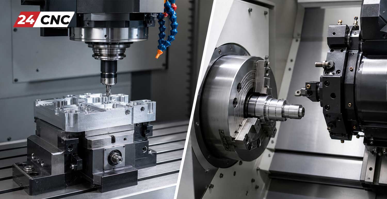
The modern manufacturing world is entirely dominated by Computer Numerical Control (CNC) technology, an industrial revolution that brought unprecedented precision, absolute repeatability, and mass-scale efficiency to the shop floor. For any manufacturing engineer, machinist, procurement specialist, or workshop owner, understanding the core machinery at a granular level is paramount to maintaining a competitive edge. At the very center of this complex ecosystem are two primary workhorses: the CNC Mill (Machining Center) and the CNC Lathe (Turning Center). While both utilize highly programmable automation to subtract material and shape raw billets into finished parts, their fundamental architectures, kinematics, and primary applications are distinctly different.
In this comprehensive, 1500+ word guide, we will deeply dissect the anatomy of these complex machines, comparing the main components of a CNC mill versus a CNC lathe. By understanding the mechanical, hydraulic, and electronic building blocks, you can optimize your machining processes, calculate better return on investment (ROI) for equipment purchases, and troubleshoot complex maintenance issues far more effectively. For a broader, higher-level overview of all machine types across the industry, you can also review our complete breakdown of the essential components of a CNC machine.
Core Architecture and Kinematics: The Fundamental Difference
The primary, most defining distinction between milling and turning lies in the kinematic relationship between the cutting tool and the workpiece. This relationship dictates the entire structural design of the machine.
- CNC Mill (Cartesian Kinematics): In a milling operation, the workpiece generally remains stationary on a worktable (or moves slowly along linear/rotary axes for positioning), while a multi-fluted cutting tool rotates at extremely high speeds. Mills map primarily to a standard Cartesian coordinate system $(X, Y, Z)$. They are explicitly designed to machine prismatic parts—components with flat surfaces, deep slots, intricate pockets, and complex 3D surface geometries.
- CNC Lathe (Cylindrical Kinematics): Conversely, in a turning operation, the raw material (the workpiece) is gripped tightly and rotates at high RPMs, while a single-point cutting tool remains rotationally stationary, translating linearly along specific axes to shave off material. Lathes map better to cylindrical coordinates $(r, \theta, z)$ but are programmed in $X$ (diameter) and $Z$ (length). They are perfectly suited for symmetrical, cylindrical parts such as drive shafts, bearing rings, flanges, and threaded cylinders.

The Detailed Anatomy of a CNC Mill
A CNC milling machine (often referred to as a Vertical Machining Center or VMC, or Horizontal Machining Center or HMC) is built for massive structural rigidity and dynamic multi-axis interpolation. To achieve this, it relies on several specialized, heavy-duty components designed to handle varying lateral and axial cutting loads.
The Spindle Assembly
The spindle is the absolute heart of the milling machine. It houses the powerful AC motor system that drives the rotation of the cutting tool. The engineering within a spindle is highly advanced. High-speed spindles used for aluminum or mold-making can exceed $20,000$ to $30,000$ RPM, relying on ultra-precision ceramic angular contact bearings to prevent thermal expansion. Alternatively, high-torque spindles geared for cutting Inconel or titanium operate at lower speeds (e.g., $4,000$ to $8,000$ RPM) but deliver massive cutting forces. The spindle includes a precision ground taper—such as CAT40, BT40, or the highly rigid HSK-63—to securely hold tool holders via a hydraulic drawbar system. Many modern spindles also feature Coolant Through Spindle (CTS) technology, pumping high-pressure coolant (up to $1,000$ PSI) directly through the tool to evacuate chips from deep holes.
The Worktable, Saddles, and Linear Axes
The worktable is a rigid, perfectly flat cast-iron surface (typically featuring T-slots) where the raw material, vises, or custom fixtures are clamped securely. In a standard 3-axis VMC, the kinematic motion is divided across the linear axes:
- $X$-Axis: Moves the table left and right longitudinally.
- $Y$-Axis: Moves the saddle (which carries the table) forward and backward, or moves the entire spindle column, depending on whether it is a C-frame or moving-column design.
- $Z$-Axis: Moves the heavy spindle head up and down vertically.
Advanced mills incorporate rotary axes, specifically the $A, B$, or $C$ axes, to achieve 4-axis indexing or full 5-axis simultaneous machining. This allows the cutting tool to approach the workpiece from practically any angle, essential for aerospace impellers or medical implants.
Automatic Tool Changer (ATC)
To maximize completely unattended “lights-out” efficiency, CNC mills are equipped with an Automatic Tool Changer (ATC). Depending on the machine size, ATCs can be umbrella-style (typically holding 10-20 tools) or high-speed twin-arm cam-driven chain magazines (holding anywhere from 30 to over 120 tools). The ATC automatically swaps tools (end mills, heavy face mills, tiny taps) into the spindle mid-program based on the G-code instructions. A highly tuned swing-arm ATC can perform a chip-to-chip tool change in less than $2.5$ seconds.

The Detailed Anatomy of a CNC Lathe (Turning Center)
CNC lathes focus heavily on rotational stability, raw torque, and turning dynamics. Their components are structurally designed to grip cylindrical stock tightly and resist heavy, continuous cutting pressure applied along a single primary axis.
The Headstock, Main Spindle, and Workholding
Unlike a mill where the spindle holds the tool, the lathe spindle is housed within the massive, cast-iron headstock and holds the workpiece itself. Attached to the spindle nose is the workholding device. The most common is the 3-jaw hydraulic chuck, which uses a hydraulic actuator at the rear of the spindle to pull a drawtube, closing the hardened jaws around the raw billet with thousands of pounds of clamping force. Collet chucks are also widely used for smaller, high-precision bar stock. The main spindle on a lathe must deliver tremendous low-end torque, especially when facing or turning large diameter steel billets, as the cutting speed requires constant surface speed calculations (CSS) by the controller.
The Tool Turret (and Live Tooling)
Instead of an ATC carousel, the vast majority of CNC lathes utilize a highly robust, indexing tool turret. This heavy, multi-sided block (often holding 10, 12, or 24 tools) holds various turning, facing, grooving, and threading tools. When a tool change is commanded ($T0101, T0202$), a servo motor rapidly unclamps, indexes (rotates), and re-clamps the turret using a high-precision Curvic coupling to bring the correct cutting tool into the active cutting position. Advanced turrets utilize BMT or VDI tooling standards and feature “live tooling.” Live tools are essentially miniature milling spindles driven by a motor inside the turret, allowing the lathe to drill cross-holes, mill flats, or tap threads off-center while the main chuck precisely locks the spindle using a $C$-axis.
The Slant Bed, Saddle, and Tailstock
Modern CNC lathes typically utilize a “slant bed” design (often cast at a 30, 45, or 60-degree angle). This heavy Meehanite cast-iron foundation provides extreme rigidity, better ergonomics for the operator, and crucially, allows hot metal chips and coolant to fall away from the linear guideways effortlessly. The saddle rides along these bed ways on the $Z$-axis (parallel to the workpiece), carrying the cross-slide which moves along the $X$-axis (perpendicular to the workpiece to control the turning diameter).
For long workpieces where the length-to-diameter ratio exceeds standard limits (e.g., $L/D > 3$), a tailstock is absolutely necessary. Sitting opposite the headstock, the tailstock extends a hydraulic quill with a Morse Taper “live center” to firmly support the far end of the spinning shaft, preventing dangerous part deflection and harmonic chatter during heavy roughing cuts.
Shared Vital Components in Both CNC Systems
While the mechanical cutting architectures and coordinate systems differ vastly, the electronic hardware and control software powering both CNC mills and lathes share a common, highly sophisticated DNA.
The CNC Control System (The Brains of the Operation)
The CNC control system is the undisputed brain of the machine tool. It reads the alphanumeric part program (generated by CAM software) and translates it into synchronized electrical signals that command the servo amplifiers and motors. A highly popular, industry-standard example is the Fanuc™ controller, globally renowned for its multi-decade reliability, macro programming capabilities, and microsecond processing speeds. The controller continuously calculates complex interpolations, manages tool wear offsets, and executes safety logic via the PLC. If you are deeply curious about how this specific alphanumeric translation works under the hood, read our comprehensive guide on how a CNC controller interprets G-code and M-code.
Servo Motors and Precision Ball Screws
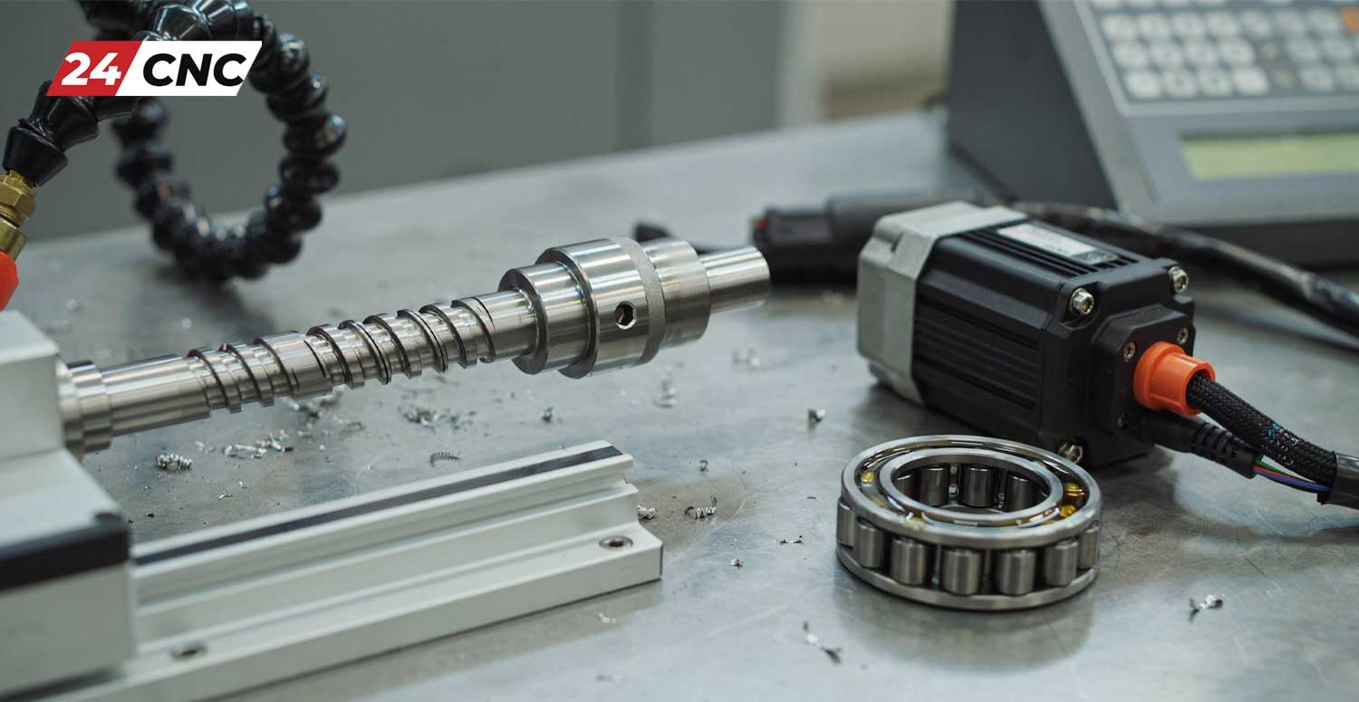
To accurately move the exceptionally heavy cast iron axes (which can weigh thousands of pounds) with microscopic precision, CNC machines completely rely on high-torque servo motors directly coupled to precision ground ball screws. The servo motors provide the rapid rotational force. The mathematical relationship governing the linear force generated is roughly $T = \frac{F \cdot P}{2 \pi \eta}$ (where $T$ is torque, $F$ is linear force, $P$ is the ball screw pitch, and $\eta$ is efficiency). The ball screw, packed with perfectly spherical ball bearings, converts that motor rotation into incredibly smooth, backlash-free linear motion, allowing the machine to feed a tool at hundreds of inches per minute without losing accuracy.
Feedback Systems (Rotary Encoders and Linear Scales)
Unlike open-loop stepper systems found in hobby routers, industrial CNC machines operate strictly on closed-loop feedback systems. To ensure the machine axis actually moved exactly where the Fanuc™ or Siemens controller commanded it to go, high-resolution rotary encoders (often mounted directly to the back of the servo motor) or glass linear scales (mounted directly to the machine axes) are utilized. These optical or magnetic sensors constantly feed exact, real-time positional data back to the controller—often millions of pulses per revolution—dynamically adjusting for minute thermal deviations and mechanical wear, ensuring final part tolerances can be held as tight as $\pm 0.0001$ inches ($\pm 2.5$ microns).
Technical Comparison Table: CNC Mill vs. CNC Lathe
To clearly summarize these vast structural and operational distinctions, please refer to this detailed technical comparison table for quick reference on the shop floor:
| Component / Feature | CNC Mill (Machining Center) | CNC Lathe (Turning Center) |
|---|---|---|
| Workpiece Motion | Stationary in a vise, or slow linear/rotary indexing (e.g., trunnion table). | Rotates at high continuous RPM in a hydraulic chuck or collet. |
| Cutting Tool Motion | Rotates at high RPM in the spindle; translates $X, Y, Z$. | Rotationally stationary (unless live tooling); translates linearly against the part. |
| Tool Storage System | Automatic Tool Changer (ATC) carousel or chain (10 to 120+ tools). | Servo-driven Indexing Tool Turret (8 to 24 stations). |
| Primary Axes | $X, Y, Z$ (Linear), Optional $A, B, C$ (Rotary). | $X, Z$ (Linear), Optional $C$ (Spindle Indexing), $Y$ (Off-center milling). |
| Ideal Part Geometry | Prismatic blocks, engine blocks, aerospace brackets, complex 3D molds. | Cylindrical shafts, threaded fasteners, custom washers, custom pulleys. |
Frequently Asked Questions (FAQ)
Can a CNC Lathe perform milling operations?
Yes, absolutely. Many modern CNC lathes are categorized as advanced “Turning Centers” or multi-tasking “Mill-Turn” machines. They come factory-equipped with “live tooling” mounted on the turret and a highly precise $C$-axis on the main spindle. This allows the controller to stop the rapid rotation of the workpiece, index it to a specific degree, and use small rotating end mills or drills to create off-center holes, flats, or keyways without moving the part to a separate milling machine.
Which machine is fundamentally easier to program, a mill or a lathe?
Generally speaking, a standard 2-axis CNC lathe is considered significantly easier to program manually via G-code than a standard 3-axis mill. This is because on a lathe, you are only managing the $X$ (diameter) and $Z$ (length) planes to create symmetrical profiles. Milling requires managing three simultaneous linear planes, often with complex circular interpolations ($G02, G03$). However, the difficulty flips when discussing complex multi-axis mill-turn machines; these are among the most mathematically difficult machines to program and heavily rely on sophisticated CAD/CAM software suites and custom post-processors.
Do mills and lathes use the exact same types of servo drives and motors?
Yes, the fundamental electronic technology behind the AC servo motors and servo amplifiers (drives) is identical. Global manufacturers like Fanuc, Siemens, Yaskawa, and Mitsubishi produce drives that can be seamlessly configured via software parameters for either a milling or turning application. The main physical difference lies in the engineering sizing of the motors; a lathe’s $Z$-axis moving a massive turret and saddle might require a higher-torque servo than a small VMC’s $X$-axis table.
Understanding the fundamental, component-level anatomy of CNC mills and lathes drastically empowers modern manufacturers to select the absolutely correct tool for the specific job at hand. While mills excel at handling prismatic complexity and lathes completely dominate cylindrical efficiency and speed, both remain indispensable, foundational pillars of modern industry. They share advanced, closed-loop electronic control technologies that continuously push the boundaries of what is possible in precision engineering and global manufacturing.
Keep Your CNC Machines Running at Absolute Peak Performance
Whether you are tasked with maintaining a $20,000$ RPM high-speed VMC or a heavy-duty, slant-bed turning center, utilizing OEM-grade, verified replacement parts is absolutely critical for maintaining micron-level precision and preventing catastrophic downtime. From advanced multi-axis control systems to high-torque servo motors and ultra-precise absolute encoders, we have your entire maintenance schedule covered.
Leave a comment
Your email address will not be published. Required fields are marked *