

For any CNC technician, maintenance engineer, or retrofitting enthusiast, the electrical cabinet is the heart of the machine. However, opening that cabinet often reveals a daunting maze of colored wires, relays, terminal blocks, and circuit boards. The key to navigating this labyrinth is knowing how to read and understand a CNC control panel wiring diagram. Without this skill, troubleshooting becomes a dangerous guessing game, and retrofitting becomes impossible.
In this comprehensive guide, we will deconstruct CNC electrical schematics, teaching you the language of industrial electronics. Whether you are working with a Fanuc™ controller, a Siemens system, or a DIY build, the fundamental principles of reading these “maps” remain the same.
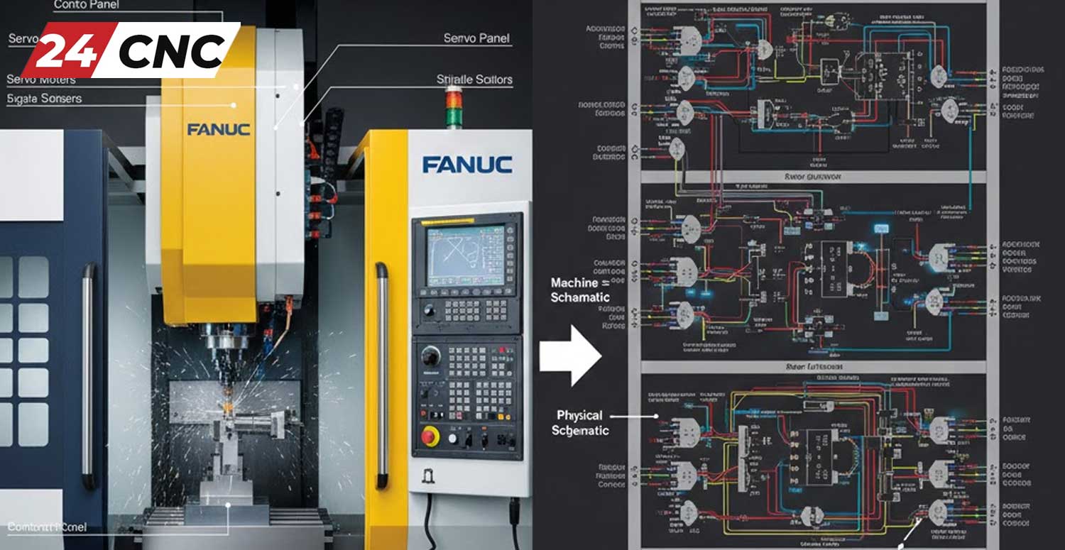
The Importance of the “Map”: Why You Must Master Schematics
A wiring diagram is not just a drawing; it is the logical representation of the machine’s physical reality. It tells you exactly where power enters, how it is transformed, where the logic signals originate, and which device executes the command. Mastering this skill allows you to:
- Diagnose Faults Quickly: Instead of checking every wire, you can trace the circuit on paper to pinpoint the likely failure point.
- Safely Replace Components: When swapping out a power supply or a drive, the diagram ensures you connect the new unit correctly, preventing catastrophic damage.
- Perform Retrofits: Upgrading an old machine requires understanding the existing I/O structure to integrate modern controls.
1. Decoding the Language: Symbols and Standards
The first barrier to understanding a diagram is the symbology. CNC diagrams generally follow one of two major standards: IEC (International Electrotechnical Commission), common in Europe and Asia (Siemens, Fanuc™), or NEMA (National Electrical Manufacturers Association), common in North America.
Common Symbols You Will Encounter
While we cannot list every symbol, these are the critical components found in almost every CNC panel:
- Contacts (NO/NC): The building blocks of logic. “Normally Open” (NO) switches close when activated; “Normally Closed” (NC) open when activated. These are ubiquitous in safety circuits and switches.
- Coils/Relays: Usually represented by a circle or a rectangle. When energized, they switch the associated contacts.
- Protection Devices: Look for symbols representing fuses and breakers. In many schematics, a fuse is shown as a rectangle with a line through it or a wavy line.
- Transformers: Represented by two facing coils, indicating the step-down of voltage (e.g., 220V AC to 24V AC).
2. Following the Power: The High-Voltage Section
When reading a diagram, standard practice is to read from left to right and top to bottom. The logic almost always starts with the incoming power.
Main Disconnect and Distribution
The diagram will start with the 3-phase incoming power (L1, L2, L3). Follow these lines. You will typically see them pass through a main breaker and a noise filter. From there, the power is distributed to:
- Servo Drives and Spindle Inverters: These require high voltage. If you are troubleshooting a servo motor issue, trace the high-voltage lines from the drive back to the contactor.
- DC Power Supplies: The diagram will show a branch going to a Power Supply Unit (PSU). This unit converts AC to DC (usually 24V) to run the computer and sensors.
Pro Tip: Always verify the power cables on the diagram against the physical labels on the wires. In high-quality CNC machines, wire numbers are printed directly on the insulation.

3. The Nervous System: Control Logic and I/O
Once power is established, the diagram shifts to the “brains” of the operation. This is where 24V DC logic reigns supreme. This section of the schematic explains how the controller talks to the machine.
Inputs (The Senses)
Inputs are signals sent to the controller. On the diagram, look for the I/O module section. You will see lines connected to:
- Limit switches (preventing over-travel).
- Pressure sensors (hydraulic/pneumatic).
- Panel buttons (Cycle Start, Feed Hold).
Outputs (The Actions)
Outputs are signals sent from the controller. The diagram will show these wires leading to:
- Relay coils (to turn on coolant pumps).
- Solenoid valves (to change tools).
- Lamps and indicators on the keyboard/panel.
4. Critical Sub-Systems: Feedback and Motion
Perhaps the most complex part of a CNC wiring diagram involves the motion control loops. This is where precision happens.
Encoder Feedback Loops
Servo motors rely on feedback to know their position. On the diagram, look for shielded cables connecting the motor to the drive or the CNC main board. These are often labeled as “Pulse Coder” or “Encoder.”
Because these signals are sensitive to interference, the diagram usually indicates grounding points for the shield. If you are experiencing “drift” or position errors, check the encoder cables on the schematic to ensure the shielding is terminated correctly.
Handwheel (MPG) Wiring
The Manual Pulse Generator (MPG) is the handwheel used for manual jogging. The wiring diagram for the handwheel is specific; it involves 5V power, ground, and two signal phases (A and B). Misinterpreting this section of the diagram is a common cause of “jerky” manual movement.
5. Understanding Brand-Specific Nuances
Not all diagrams are created equal. A Mitsubishi manual looks very different from a Siemens one. Here is a technical comparison of how major brands structure their electrical documentation.
| Feature | Fanuc (Japanese Standard) | Siemens (European Standard) | Mitsubishi (Japanese Standard) |
|---|---|---|---|
| Schematic Logic | Often uses “Ladder” logic representation heavily integrated with hardware diagrams. | Strict IEC standards. Very structured, page-based referencing (e.g., /12.4). | Hybrid approach. Strong focus on “Sink/Source” I/O configuration diagrams. |
| I/O Naming | X (Input) / Y (Output) addresses commonly used. | I (Input) / Q (Output) notation (e.g., I0.0, Q4.2). | X (Input) / Y (Output) usually in Hexadecimal. |
| Connector Density | High. Uses proprietary Honda connectors frequently. | Modular. Uses standardized terminal blocks and PROFIBUS/PROFINET. | Compact. Often integrates I/O directly into drives. |
| Wire Identification | Numbering is critical; rarely uses color coding for function. | Wire color often dictates voltage (Red=AC, Blue=DC). | Similar to Fanuc, heavy reliance on pinout charts. |
Practical Troubleshooting Scenarios
Scenario A: The Emergency Stop Loop
The machine won’t start. You open the diagram. Find the “E-Stop” or “Emergency” circuit. It is almost always a series circuit involving the operator panel button, limit switches, and the drive enable signal. By using a multimeter and the diagram, you can test for continuity across each switch in the chain (represented as NC contacts) until you find the open link.
Scenario B: LCD Screen is Dark
If your LCD screen is blank, locate the “Video” or “Display” section of the schematic. Check for two things: the 24V DC power input to the screen and the video signal cable coming from the CNC graphics card. The diagram will give you the pinout to test if voltage is reaching the unit.
Scenario C: Spindle Cooling Fan Failure
Overheating spindle? Find the fan on the diagram. Is it 220V AC or 24V DC? Is it switched by a relay or connected directly to the main bus? The diagram answers this instantly, allowing you to check the fuse or the fan motor itself.
Conclusion: Patience is Key
Reading a CNC control panel wiring diagram is a skill that improves with practice. Start by identifying the major components: the controller, the drives, and the power supply. Trace the lines one by one. Remember, at 24CNC, we specialize in providing the high-quality parts—from connectors to complete control systems—that populate these diagrams. Understanding your machine’s schematic is the first step toward true mastery of CNC maintenance.
Frequently Asked Questions (FAQ)
What is the difference between “Sink” and “Source” wiring in CNC diagrams?
This refers to how current flows in DC circuits. In Source wiring (PNP), the module provides the positive voltage (+) to the load. In Sink wiring (NPN), the module provides the path to ground (-). Getting this wrong in a diagram interpretation can blow your I/O card.
Why are some lines dashed and others solid in the schematic?
Solid lines usually represent physical wires located inside the cabinet. Dashed lines often represent external wiring (field wiring) going to motors or sensors outside the cabinet, or they may indicate a mechanical linkage rather than an electrical connection.
I lost my machine’s wiring diagram. Can I use a generic one?
Generally, no. While the pinouts for standard components like a Siemens controller or a Fanuc amplifier are standard, the specific machine wiring (safety loops, button logic) is unique to the machine builder (OEM). You should try to contact the manufacturer or look for diagrams of identical model numbers.
What do the numbers on the wires mean?
These are “wire numbers” or “potential numbers.” In a professional diagram, every wire that is electrically common (connected together) shares the same number. If a wire passes through a switch or a load, the number changes. This is vital for tracing circuits with a multimeter.
Need Parts to Complete Your Circuit?
Whether you are replacing a faulty encoder, upgrading a servo drive, or sourcing hard-to-find connectors for your Fanuc or Siemens system, 24CNC has the inventory you need. Don’t let a wiring issue stop your production.
Leave a comment
Your email address will not be published. Required fields are marked *