
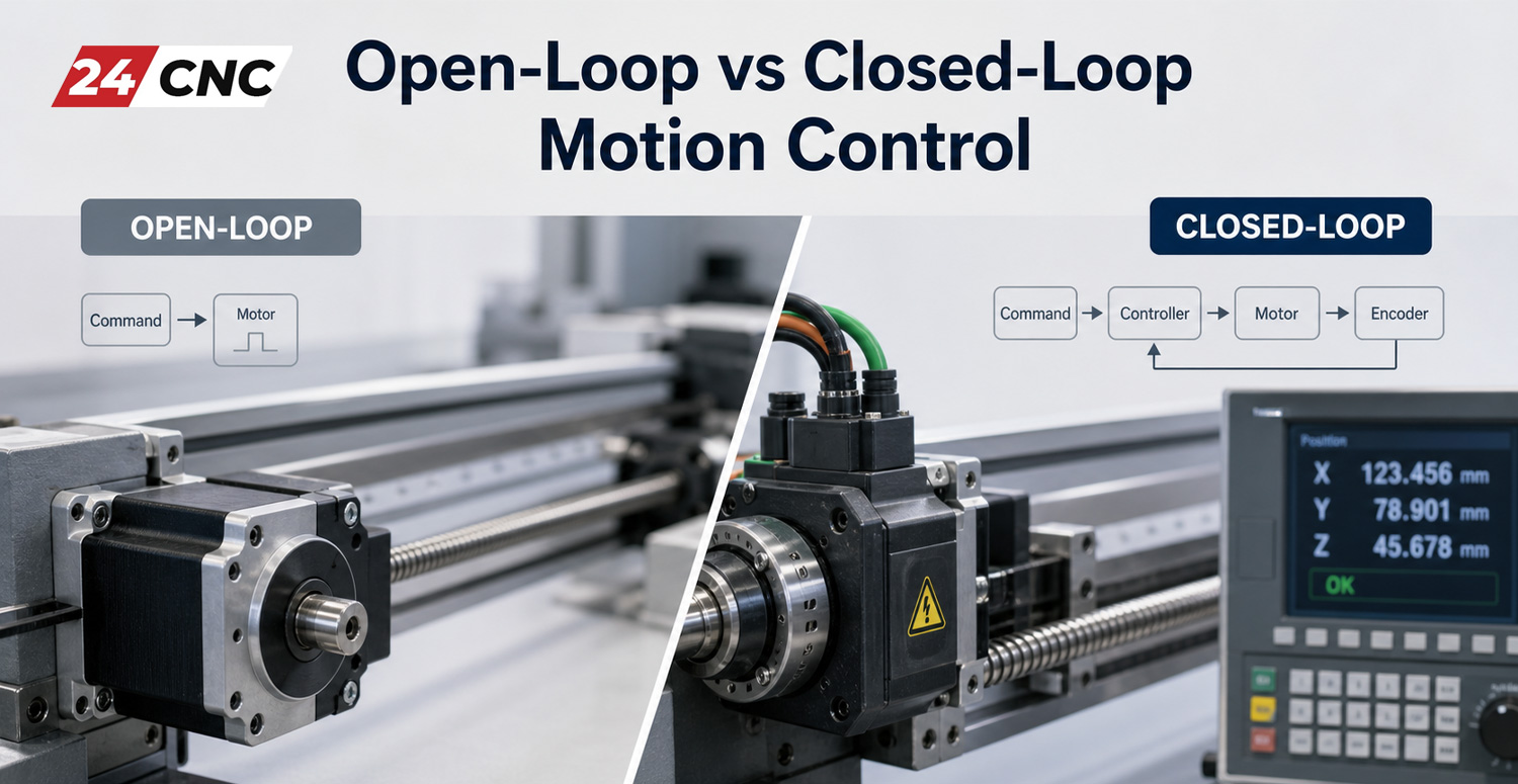
In modern industrial automation, robotics, and CNC machine design, selecting the motion control topology is one of the most critical mechanical and electrical engineering decisions. The fundamental distinction between open-loop motion control and closed-loop motion control dictates positional accuracy, high-speed dynamic torque, thermal efficiency, failure modes, and total system cost. While open-loop systems rely on the assumption of motion, closed-loop architectures measure, verify, and continuously rectify position and velocity in real time. For engineers choosing components across an entire CNC control system, understanding the electromechanical trade-offs between these two control paradigms is necessary to maximize operational throughput without incurring unnecessary capital expense.
Whether you are designing a compact desktop engraving machine, retrofitting a production-grade 5-axis vertical machining center, or configuring high-speed pick-and-place robotics, this engineering guide analyzes open-loop and closed-loop control from theoretical transfer functions down to physical sensor integration, mathematical servo tuning, and industrial drive architectures.
Foundational Architecture & Control Theory
Every motion system converts commanded setpoints (typically generated by a motion planner, PLC, or CNC interpolator) into mechanical work. The presence or absence of a feedback loop between the mechanical load and the motion controller defines the fundamental operational philosophy of the system.
The Open-Loop Control Model
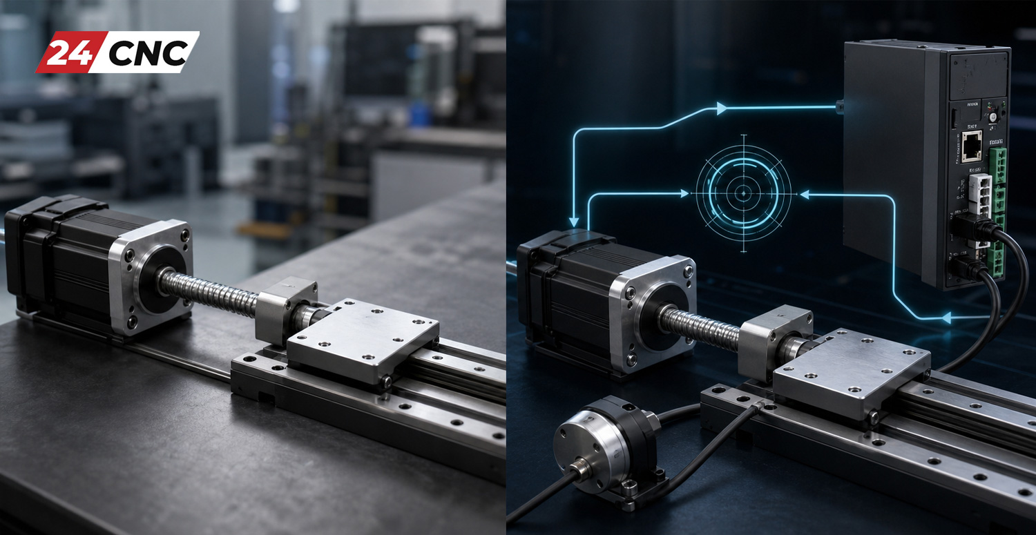
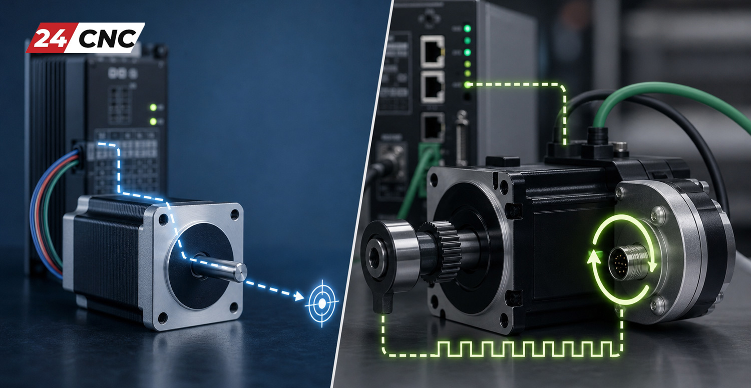
An open-loop system operates on a direct feedforward pipeline: Setpoint \to Controller \to Drive Amplifier \to Actuator \to Mechanical Output. The controller issues a stream of pulse and direction signals or continuous velocity commands based on calculated target positions. The drive executes the power modulation necessary to index the motor shaft (most commonly a two-phase or three-phase hybrid stepper motor), and the controller assumes that the commanded position matches the actual physical position of the axis.
Mathematically, the open-loop transfer function G(s) relates output displacement Y(s) to input command R(s) purely through the plant dynamics without error subtraction:
Y(s) = G(s) \cdot R(s)
Because there is no feedback transducer measuring load position, the system cannot verify whether the command was executed. If an instantaneous mechanical resistance exceeds the motor’s pull-out torque, or if an aggressive acceleration profile forces the rotor outside its magnetic detent angle, the motor will stall or drop steps. The motion controller remains blind to this positional deficit, accumulating permanent positioning errors throughout the program cycle.
The Closed-Loop Control Model
A closed-loop system incorporates active feedback sensors—such as a rotary encoder, resolver, or linear optical scale—to measure the actual mechanical displacement and velocity of the motor shaft or machine table. This measured variable is continuously fed back and subtracted from the instantaneous reference command, creating a dynamic error signal:
e(t) = r(t) – y(t)
The feedback loop adjusts drive current and voltage to drive this error signal toward zero. The closed-loop transfer function T(s) in the Laplace domain is governed by:
T(s) = \frac{C(s) G(s)}{1 + C(s) G(s) H(s)}
Where C(s) represents the loop controller (typically a proportional-integral-derivative, or PID, filter), G(s) represents the amplifier and actuator dynamics, and H(s) represents the feedback sensor transfer function. This dynamic compensation eliminates steady-state errors, rejects external mechanical disturbances, and ensures that the machine follows its toolpath regardless of cutting forces, friction variations, or thermal expansion.
Actuator Technologies: Steppers vs. Servos
The operational divide between open-loop and closed-loop motion control is closely linked to motor design. While hybrid steppers dominate open-loop systems, closed-loop architectures generally deploy permanent-magnet AC or brushless DC servo motors or closed-loop “smart” steppers.
Hybrid Stepper Motors (Open-Loop Workhorses)
Hybrid stepper motors utilize high-pole-count rotors (typically 50 magnetic teeth, yielding 200 full steps per revolution or 1.8^\circ step angles). When energized by microstepping drives, current is apportioned between stator phases in a sinusoidal distribution, dividing each physical step into fractional increments (e.g., 1/8, 1/16, or 1/32 microstepping).
- High Holding Torque at Low Speeds: Stepper motors produce exceptional torque at zero and near-zero RPM without requiring an active control loop. This makes them ideal for positioning applications that hold static loads.
- Torque Roll-Off at Speed: Because of high stator inductance and back-electromotive force (Back-EMF), the usable torque of a stepper motor drops rapidly as shaft speed increases. At speeds above 800\text{–}1200\text{ RPM}, available torque often plummets by more than 70\%.
- Continuous Current Draw: Standard open-loop drives push full rated current through the motor windings regardless of the external mechanical load. This leads to high thermal dissipation, causing stepper motors to operate at casing temperatures exceeding 70^\circ\text{C} to 85^\circ\text{C} even during idle periods.
- Resonance and Oscillation: Stepper rotors act as a mass-spring system, making them prone to mechanical resonance between 100\text{ and }300\text{ RPM}. If commanded at these frequencies without microstepping smoothing, severe audible noise, loss of synchronization, and sudden stalling can occur.
Brushless AC Servos (Closed-Loop Precision)
Modern servo systems integrate low-pole-count rotors (4 to 10 permanent magnet poles) with three-phase stator windings. Because the rotor poles are widely spaced, the motor cannot step autonomously; it requires continuous electronic commutation driven by real-time encoder feedback processed by an industrial servo amplifier and drive.
- Flat Torque Curve: AC servos deliver constant torque from zero RPM up to their base rated speed (typically 3000\text{–}6000\text{ RPM}), providing broad dynamic bandwidth for high-speed machining.
- Peak Torque Capability: A servo motor can output 300\% to 400\% of its continuous rated torque for brief transient windows (acceleration/deceleration spikes or interrupted cutting loads).
- Current on Demand: Closed-loop servo amplifiers draw only the current necessary to balance the immediate external load. When idle, holding current drops close to zero, keeping motors significantly cooler and prolonging insulation life.
For engineers troubleshooting drives and diagnosing internal error codes across multi-axis installations, our comprehensive guide on CNC servo amplifiers and drives covers drive sizing, parameter setup, and fault isolation.
Deep Technical Comparison
The following engineering matrix compares open-loop and closed-loop motion control across key electrical, mechanical, and operational performance metrics.
| Performance Criterion | Open-Loop System (Standard Stepper) | Closed-Loop Stepper (“Smart Stepper”) | Closed-Loop AC Servo System |
|---|---|---|---|
| Positional Verification | None (Assumed position) | Yes (Integrated encoder on motor) | Yes (High-resolution rotary/linear encoder) |
| Stall Recovery & Fault Detection | Impossible; job continues with offset errors | Detects lag, adjusts current, trips alarm if stuck | Instantly triggers following-error alarm (E-Stop) |
| Top Usable Operating Speed | 600\text{ to }1000\text{ RPM} | 1000\text{ to }2000\text{ RPM} | 3000\text{ to }6000\text{ RPM} |
| Torque Output Dynamics | High static torque, steep decay at speed | Full holding torque, moderate decay curve | Constant rated torque + 300\% peak surge |
| Thermal Management | Hot (100\% continuous current always) | Moderate (Current scales with torque load) | Cool (Current strictly matches load) |
| Control Loop Tuning | None required (Plug & play setup) | Minimal (Factory tuned for standard inertia) | Critical (Requires PID, velocity, inertia tuning) |
| Audible Resonance & Jitter | Noticeable mid-band resonance / singing | Low (Field-oriented current dampens hum) | Near-silent motion across all velocities |
| Relative System Cost | Lowest () | Moderate () | Higher () |
Feedback Topologies: Semi-Closed vs. Fully Closed Loops
When implementing closed-loop motion control, the mechanical location of the feedback transducer is critical. Industrial CNC systems fall into two distinct structural classifications: semi-closed loop and fully closed loop.
Semi-Closed Loop (Motor-Mounted Feedback)
In a semi-closed loop architecture, the encoder is mounted directly to the rear of the motor shaft. An incremental rotary encoder or high-resolution absolute encoder reads the angular rotation of the rotor.
- Advantages: Extremely high dynamic stiffness, excellent servo bandwidth, and straightforward PID tuning. Because the feedback loop does not include the compliance, backlash, or torsional deflection of mechanical couplings and ball screws, high proportional gains can be applied without causing servo hunting or resonance.
- Disadvantages: The system is blind to non-linear mechanical errors occurring downline of the motor shaft. Mechanical backlash in ball nuts, torsional twist in drive shafts, wear on linear guide ways, and thermal expansion of the ball screw as the machine warms up are not measured or compensated for.
Fully Closed Loop (Direct Load-Mounted Feedback)
In a fully closed loop topology, the position of the moving axis is measured directly at the machine table using an external optical linear glass scale or magnetic tape scale, bypassing the mechanical drivetrain entirely. For detailed mounting tolerances and alignment procedures, refer to our step-by-step linear scale calibration and installation guide.
The feedback loop directly encompasses mechanical inaccuracies: if a ball screw exhibits 25\ \mu\text{m} of axial backlash during a reversal move, the controller detects that the table has not yet moved and drives the motor forward until the linear scale registers the correct coordinates. Understanding the operational purpose of feedback transducers is essential here; review what the function of an encoder is in industrial automation to examine physical pulse generation.
Dual-Loop Architecture
To prevent mechanical compliance and backlash from inducing servo instability in fully closed-loop machines, high-end controllers—such as Fanuc™ 31i, Siemens Sinumerik ONE, and Heidenhain TNC7—utilize dual-loop control. The primary inner velocity loop closes around the high-resolution motor-mounted encoder, maintaining high-bandwidth damping and preventing high-frequency oscillations. Simultaneously, an outer position loop closes around the linear glass scale, correcting for low-frequency position drift, mechanical thermal growth, and pitch errors.
Mathematical Tuning of Closed-Loop Systems (PID & Feedforward)
Unlike open-loop systems that require zero mathematical tuning, closed-loop systems require parameter configuration to achieve dynamic stability. The foundation of closed-loop drive architecture is the nested triple-loop: the Current Loop (inner, 10\text{–}40\text{ kHz} sampling rate), the Velocity Loop (middle, 2\text{–}8\text{ kHz} sampling rate), and the Position Loop (outer, 1\text{–}2\text{ kHz} sampling rate).
The output of the position-velocity controller is governed by standard PID control laws with velocity and acceleration feedforward:
u(t) = K_p e(t) + K_i \int_0^t e(\tau) d\tau + K_d \frac{de(t)}{dt} + K_{ffv} \frac{dr(t)}{dt} + K_{ffa} \frac{d^2r(t)}{dt^2}
Where:
- K_p (Proportional Gain): Generates a restoring force directly proportional to the position error e(t). Raising K_p stiffens the axis and reduces tracking error, but excessive gain causes overshoot and high-frequency acoustic hunting.
- K_i (Integral Gain): Sums residual positional errors over time to eliminate steady-state offset caused by constant external friction or gravitational loads on vertical axes. Excessive K_i introduces phase lag and cyclical low-frequency oscillation.
- K_d (Derivative Gain): Reacts to the rate of change of the error signal, providing virtual viscous damping. It counteracts overshoot from K_p, but is sensitive to high-frequency sensor noise.
- K_{ffv} (Velocity Feedforward): Bypasses the position error loop by calculating expected velocity directly from commanded trajectory profiles (dr/dt), reducing dynamic following error during constant-speed moves to near zero.
- K_{ffa} (Acceleration Feedforward): Directly injects motor torque based on planned axis acceleration (d^2r/dt^2) multiplied by the system’s total reflected inertia (J_{\text{total}}), overcoming rotor and table inertia without requiring error accumulation.
If your closed-loop system experiences erratic following-error alarms or position oscillation during high-speed moves, shielded cable degradation is often to blame. Review our troubleshooting procedures to fix shielded cable noise in servo encoders to isolate electrical interference from tuning instabilities.
Mechanical Precision, Pitch Error & Backlash Limits
A common misconception in CNC engineering is that closed-loop motion control can compensate for poor mechanical construction. In reality, closed-loop performance is directly bounded by the rigidity and accuracy of the underlying mechanical components.
Mechanical Backlash and Lost Motion
If an axis experiences mechanical backlash from a worn ball nut, reversing direction results in a period where the motor shaft rotates without moving the table. In open-loop stepper systems, this motion is lost permanently, creating oval circular interpolations and undersized bosses. While software backlash compensation can help, mechanical wear requires continuous adjustment; see our guide to fix and compensate CNC axis backlash for mechanical preload and software mapping methods.
In closed-loop systems, backlash introduces a non-linear deadband phase lag. If high proportional gains are commanded while the table sits in this deadband, the motor will oscillate violently across the clearance gap—a destructive phenomenon known as limit-cycle oscillation.
Drive Transmission Quality
To maximize the performance of closed-loop servo systems, the mechanical drive components must provide predictable, low-friction motion. Comparing C3, C5, and C7 ball screw precision grades highlights how pitch error variations directly influence positioning accuracy, regardless of whether you run open or closed loops.
Engineering Selection Framework: When to Choose Open vs. Closed Loop
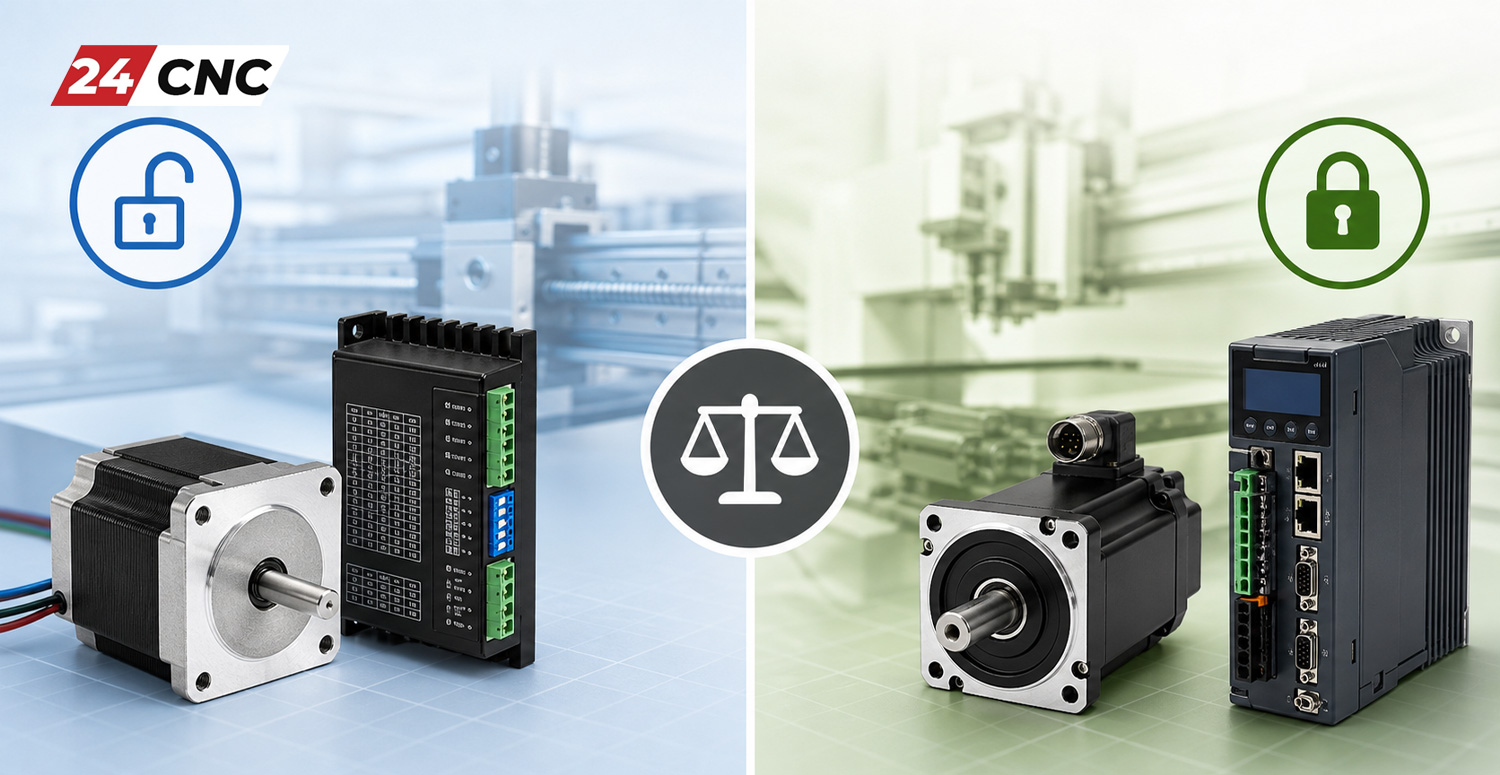
Choosing between open-loop and closed-loop control requires balancing cost, mechanical precision, axis acceleration, and the risk of part rejection.
Choose Open-Loop Stepper Control When:
- Mechanical Loads are Predictable and Low: The toolhead does not encounter dynamic shock loads (e.g., 3D printers, laser cutters, plasma torches, or dispensers).
- Rapid Speeds are Modest: Traversing speeds remain under 10\text{–}15\text{ m/min} (400\text{–}600\text{ IPM}), and motor shaft speeds stay under 800\text{ RPM}.
- Budget Constraints are Stringent: The application does not justify high-end controllers, complex cabling harnesses, or tuning cycles.
- Holding Torque at Rest is Essential: The mechanism must lock rigidly in place without hunting or dither, such as laboratory sample stages or optical focus mounts.
Choose Closed-Loop Servo or Smart Stepper Systems When:
- High Dynamic Performance is Required: Axis velocities exceed 25\text{–}60\text{ m/min} with accelerations greater than 0.5\text{g} to 2.0\text{g}.
- Cutting Loads are High and Unpredictable: Heavy roughing cuts in hardened tool steels, titanium, or exotic composites generate high cutting forces that could stall an open-loop motor.
- Part Scrapping is Prohibitively Costly: High-value aerospace, automotive, or medical components cannot risk dropped steps going unnoticed. Closed-loop following-error triggers immediately halt the cycle to protect the workpiece.
- Kinematic Trajectory Synchronization is Essential: 4-axis and 5-axis continuous contouring requires tight tracking tolerances across all axes simultaneously. Refer to our guide on understanding CNC machine axes from 3-axis to 5-axis to see how coordinate synchronization impacts multi-axis part finishes.
Frequently Asked Questions (FAQ)
1. Can an open-loop stepper motor achieve the same positional resolution as a closed-loop servo?
Theoretical resolution must not be confused with true mechanical accuracy. While an open-loop stepper drive operating at 1/16 microstepping provides 3200\text{ pulses/revolution} (0.1125^\circ\text{ per step}), the actual rotor position can deviate by up to \pm 5\% of a full step under external loads before breaking lock. In contrast, closed-loop servo systems equipped with 20\text{-bit} or 23\text{-bit} absolute encoders divide a revolution into millions of pulses and actively correct the rotor to within single-count tolerances.
2. What is a “closed-loop stepper” and how does it bridge the gap?
A closed-loop stepper (often marketed as an “easy servo” or hybrid servo) pairs a standard high-pole hybrid stepper with a low-to-medium resolution optical or magnetic rotary encoder (typically 1000\text{–}4000\text{ PPR}). The drive runs field-oriented current control (FOC), varying the coil current based on the rotor’s actual position rather than pushing continuous full power. This eliminates lost steps, lowers heat generation, and prevents resonance while maintaining the high low-speed torque of a traditional stepper.
3. Why do servo systems experience “hunting” or high-frequency dither at standstill?
Hunting occurs when the proportional gain (K_p) or integral gain (K_i) is set too high relative to the load inertia and mechanical backlash. When the motor tries to hold zero position, high gain causes it to overshoot the target count. The feedback loop detects this new error and commands a reverse correction, which overshoots again. This creates a high-frequency micro-oscillation (100\text{–}500\text{ Hz}) that produces an audible buzz and excess motor heating. Proper PID filtering, low-pass notch filters, or deadband windows resolve this behavior.
4. Can I convert an open-loop CNC router to closed-loop without replacing the controller?
Yes. Most modern closed-loop stepper and AC servo drives accept standard 5\text{V} or 24\text{V} Step (Pulse) and Direction signals identical to open-loop stepper drives. In this setup, the closed-loop feedback path is closed entirely within the drive amplifier itself (drive-closed loop). The main CNC controller continues outputting step and direction trains, while the drive handles encoder reading and dynamic motor correction. The drive’s alarm/fault relay should be wired back into the controller’s E-stop line so the machine halts if an axis trips a following-error threshold.
5. How do magnetic and optical encoders compare in harsh machining environments?
Optical encoders provide extremely high resolution and line counts, making them the standard choice for precision machine tools. However, they are sensitive to liquid coolant ingress, oil mist, and dust on the glass disk. Magnetic encoders utilize Hall-effect or magnetoresistive sensors reading multi-pole magnetic rings; while they typically offer lower raw resolution, they are immune to coolant, oil, and dust contamination. For a detailed breakdown of environmental survivability, read our comparison on magnetic vs. optical encoders in harsh environments.
Source Industrial Motion Control Components at 24CNC
Whether you are designing an open-loop positioning system or outfitting a high-speed production line with precision AC servos, digital drives, rotary encoders, and glass scales—24CNC supplies certified, high-reliability industrial hardware backed by technical support and global delivery.
Leave a comment
Your email address will not be published. Required fields are marked *