

In high-precision machining, relying exclusively on motor-mounted rotary encoders often leaves a significant accuracy gap. Thermal expansion of ball screws, structural deflection under load, and mechanical backlash can introduce position errors that standard semi-closed loop systems cannot detect. Integrating and properly setting up linear optical or magnetic scales converts your machine into a fully closed-loop system, providing direct, micron-level positional feedback straight from the machine slide.
However, a linear scale is only as precise as its mechanical installation and electronic calibration. A scale misaligned by even a fraction of a millimeter can suffer from optical scanning errors, accelerated lip-seal wear, signal dropouts, and premature failure. In this comprehensive guide, we cover everything you need to know about linear scale selection, precision mechanical installation, cable shielding, controller parameter setup, and laser-assisted calibration.
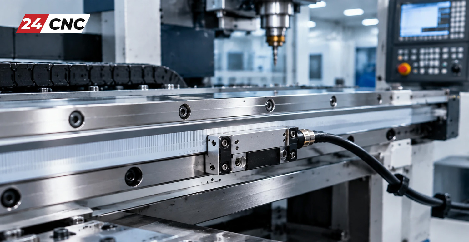
Why Linear Scales Are Critical for CNC Precision (Full Closed-Loop)
Most standard CNC machines utilize a semi-closed loop system where a rotary encoder attached to the back of the servo motor calculates axis movement based on the pitch of the ball screw. While effective for basic tolerance work, this method assumes that mechanical motion transfer is 100% rigid and predictable.
In reality, as a machine runs, cutting forces and friction generate heat. A ball screw can expand by several tens of microns over a single shift. When you introduce C3, C5, or C7 precision grade ball screws, you minimize mechanical pitch error, but you cannot eliminate thermal growth or mechanical deflection under load. Linear scales solve this by measuring the physical position of the machine table relative to the bed, completely bypassing the kinematic errors of couplings, thrust bearings, and ball screws.
Understanding the fundamental difference in feedback systems is critical. For more on feedback concepts, explore our technical breakdown on what function encoders serve in industrial automation systems.
Types of Linear Scales: Optical Glass vs. Magnetic Scales
Before beginning an installation or retrofitting project across your CNC machine axes, you must select the appropriate scale technology for your operational environment:
1. Optical Glass Linear Scales
Optical scales utilize a precision-etched glass scale grating (often with line pitches of 20 μm or smaller) and an infrared scanning reticle within the reader head. They deliver superior absolute accuracy and sub-micron resolution. However, because they rely on optical transmission or reflection, they are sensitive to liquid contamination, oil mist, and condensation. They must be enclosed in rugged aluminum extrusions protected by elastomeric lip seals and continuous clean air purging.
2. Magnetic Linear Scales
Magnetic scales use a magnetized elastomer tape bonded to a steel strip, read by a magnetoresistive or Hall-effect sensor head. They are impervious to coolant, cutting fluids, chips, and heavy dust. While historically offering slightly lower absolute accuracy than top-tier glass scales, modern magnetic scales deliver remarkable resolution suitable for harsh-environment milling, heavy turning, and grinding applications. Compare these technologies further in our analysis of magnetic vs. optical encoders in harsh industrial environments.
Pre-Installation Planning & Alignment Tolerances
Precision linear scales are precision metrology instruments encased in protective housings. Careless handling or improper mounting will distort the scale spar or destroy the scanning head optics.
Required Metrology & Assembly Tools:
- Plunger Dial Indicator / Dial Test Indicator (DTI): Resolution of 0.001 mm (1 micron) or 0.002 mm, with a sturdy magnetic base.
- Precision Parallel Blocks & Feeler Gauges: For setting standoff gaps and ride clearance.
- Torque Wrench: Calibrated for low torque ranges (typically 1.5 Nm to 5.0 Nm depending on bolt size M3–M6).
- Non-Contact Degreaser & Lint-Free Metrology Wipes: For mounting surface preparation.
- Precision Level / Straight Edge: To verify mounting substrate planar flatness.
Critical Alignment Tolerances to Maintain:
- Scale Spar Parallelism to Machine Guideway: Within 0.05 mm (0.002″) over the full travel length (ideally within 0.02 mm for high-precision finishing machines).
- Reader Head Gap (Standoff): Typically 1.0\text{ mm} \pm 0.1\text{ mm} (check manufacturer specification plastic shims).
- Reader Head Angular Tilt (Pitch, Yaw, Roll): Must not exceed \pm 0.1^\circ to prevent signal phase distortion in Sin/Cos and TTL differential waveforms.

Step-by-Step Linear Scale Mechanical Installation
Follow this systematic procedure to ensure rigid, distortion-free mounting of both the scale housing and reader head.
Step 1: Inspecting and Preparing the Mounting Substrate
The scale housing must be bolted to a machined reference surface on the machine casting. Thoroughly clean the mounting surface, stoning away any high spots, nicks, or burrs. Verify that the mounting face is straight and coplanar with the axis guideways using a dial indicator mounted on the moving table.
Step 2: Installing and Aligning the Scale Spar Housing
- Temporarily mount the scale housing using the supplied mounting slots and bolts, leaving them finger-tight.
- Attach your dial test indicator to the moving axis table and position the stylus on the precision top reference surface of the scale housing.
- Jog the axis slowly across its full stroke. Adjust the scale height at each mounting point using precision shims or adjustment set screws until the top face is parallel to the axis motion within 0.03 mm.
- Transfer the indicator stylus to the side machined reference face of the scale spar. Jog the axis again and align the lateral parallelism within 0.02 mm to 0.05 mm.
- Torque down all mounting bolts progressively from the center outward to manufacturer specs, re-checking the dial indicator at each step to ensure tightening has not introduced bow or twist.
Step 3: Mounting the Scanning (Reader) Head
- Most manufacturers provide a temporary plastic spacer or shipping clip (usually yellow, red, or blue) that locks the reader head at the correct clearance and alignment relative to the scale body. Do not remove this clip yet.
- Mount the reader head bracket to the moving machine component (such as the saddle or spindle carrier). Ensure the bracket is rigid; flimsy brackets flex under axis acceleration, introducing dynamic positioning errors.
- Fasten the reader head to its bracket. Tighten mounting screws evenly without exerting side force on the scanner body.
- Once fastened securely, slide out the plastic alignment shipping clip. Store it safely for future maintenance or transport.
- Manually jog the axis across its full length at slow speed, observing that the sealing lips deflect symmetrically without binding, pinching, or rubbing excessively against the scanner neck.
Step 4: Cable Routing, Grounding, and Signal Integrity
Linear scale signals (whether 1Vpp analog, TTL differential quadrature, or synchronous serial protocols like EnDat, Fanuc™ Serial, or Mitsubishi high-speed interface) operate at high frequencies and low voltage levels. They are highly susceptible to electromagnetic interference (EMI) generated by spindle inverters and servo drives.
- Route scale signal cables through flexible cable carriers (drag chains) in isolated channels separated from high-voltage motor power cables by at least 100 mm (4 inches).
- Ensure the braided cable shield is grounded 360 degrees at the metal connector shell entering the controller cabinet. Review our best practices on how to fix shielded cable noise in servo and encoder circuits.
- Ensure that all machine components, encoder cables, and control enclosures share a common low-impedance ground plane.
Step 5: Sealing Air (DA Air Purge) Connection
For optical glass scales in machining centers using high-pressure flood coolant, connect a clean, dry, oil-free compressed air line to the scale housing’s purge port. Maintain regulated pressure between 0.5 bar and 1.0 bar (7 to 14 PSI). This creates positive internal pressure, preventing coolant vapors, mist, and fine swarf from bypassing the elastomeric lip seals.
Linear Scale Calibration Techniques
Once mechanical installation is complete, the scale must be electronically calibrated to compensate for cosine errors, linear thermal expansion, and machine geometric deviations.
1. Linear Error Compensation (LEC)
Linear error occurs when a constant slope error is observed across the entire stroke (e.g., the axis travels 1000.025 mm when commanded to move 1000.000 mm). This is calculated by:
\text{Correction Factor (PPM)} = \left(\frac{\text{Target Length} – \text{Measured Length}}{\text{Target Length}}\right) \times 10^6
You can perform LEC using calibrated ceramic step gauges, long gauge blocks, or laser measurement equipment. Enter the calculated PPM (Parts Per Million) compensation factor into the controller’s linear compensation parameter.
2. Non-Linear Pitch Error Compensation (PEC) using Laser Interferometry
Even with high-precision linear scales, structural imperfections in machine castings cause local pitch, yaw, and Abbe offsets along the travel path. A dual-frequency laser interferometer measures position deviation at precise intervals (e.g., every 10 mm or 25 mm). The resulting error table is loaded into the CNC control system to provide point-by-point compensation across the entire axis envelope.
Controller Parameter Configuration
Integrating a direct linear measuring scale requires configuring your CNC controller from a semi-closed loop to a full closed-loop architecture.
Configuring on Fanuc Systems
On machines powered by Fanuc™ controllers (such as Series 0i, 30i/31i/32i):
- Set Parameter
1815#1 (OPTx)to1to instruct the servo software that a separate linear scale (optical/magnetic scale) is installed on the axis. - Set Parameter
1815#2 (APHDx)and relevant scale interface parameters according to the scale protocol (e.g., Fanuc Serial Interface or separate scale interface unit / SDU). - Configure the Flexible Feed Gear (F-FG) parameters (Parameters
2084and2085) to establish the exact pulse ratio between the motor encoder, linear scale pitch, and the controller’s internal detection unit. - Set dual position feedback conversion parameters (Parameters
2078,2079) to define the filtering and deadband between motor feedback and scale feedback, preventing servo hunting and oscillation.
Configuring on Siemens Systems
On machines equipped with Siemens Sinumerik controllers (828D / 840D sl):
- Access the Axis Machine Data (Axis MD).
- Set
MD30200 MA_NUM_ENCSto2(indicating dual encoder configuration: Encoder 1 on motor, Encoder 2 on linear scale). - Set
MD31000 MA_ENC_TYPE[1]to match your scale output (e.g.,1for raw incremental,4for absolute EnDat/Drive-CLiQ). - Set
MD31040 MA_ENC_IS_DIRECT[1]to1(specifying that measuring system 2 is mounted directly to the machine slide). - Configure
MD31010 MA_ENC_GRID_POINT_DISTwith the physical grid spacing of the scale (e.g.,0.020 mmfor standard 20 μm grating). - Perform an NCK Reset to initialize closed-loop control.

Technical Comparison: Feedback Technologies
| Feature / Specification | Optical Glass Scales | Magnetic Tape Scales | Motor Rotary Encoders |
|---|---|---|---|
| Loop Architecture | Full Closed-Loop | Full Closed-Loop | Semi-Closed Loop |
| Typical Accuracy Class | ±2 μm to ±5 μm / meter | ±10 μm to ±20 μm / meter | Subject to screw expansion/backlash |
| Immunity to Liquids/Chips | Moderate (Requires air purge + seals) | High (IP67 / IP68 ratings standard) | High (Housed internally in motor) |
| Maximum Measuring Length | Up to ~3,000 mm (single spar) | Up to 30+ meters (continuous reel) | Unlimited (Rotary counts) |
| Installation Sensitivity | High (Requires strict alignment) | Moderate (More forgiving gap tolerances) | None (Factory pre-installed) |
Troubleshooting Common Linear Scale Faults
When a linear scale malfunctions, errors can manifest as axis tripping, tracking alarms, or surface finish ripple. Here is how to diagnose and resolve the most common issues:
- Encoder Disconnection Alarms (e.g., Fanuc SV0385 / Siemens 25000): Check for broken internal wires in high-flex drag chain sections, loose D-sub connectors, or coolant ingress in the reader head housing. Clean the optical scale glass using pure isopropyl alcohol and a soft lint-free swab.
- Servo Oscillation and Axis “Humming”: This occurs when the controller gain is set too high for a closed-loop system, or there is excessive mechanical backlash between the motor and the scale. The motor overcorrects to satisfy the linear scale, causing high-frequency shudder. Increase the dual-feedback filter time constant or service the mechanical ball screw thrust bearings.
- Periodic Counting Errors and Inconsistent Dimensions: Indicates scale housing twist or pitch deviation. Re-check the parallelism of the scale spar with a dial test indicator along both the horizontal and vertical planes.
Frequently Asked Questions (FAQ)
Can I install a linear scale on an older CNC machine with a worn ball screw?
Yes, a linear scale directly measures table position and will compensate for pitch wear and thermal expansion. However, if mechanical backlash exceeds 0.05 mm, the servo drive may oscillate trying to find position. Mechanical backlash must be minimized before closed-loop feedback can operate smoothly.
Why is sealing air (air purge) mandatory for optical linear scales?
In CNC milling and grinding environments, atomized coolant mist and sub-micron particulate easily migrate past rubber lip seals. A steady positive pressure (0.5 to 1.0 bar) of dry, filtered air creates an outward flow barrier, keeping the internal glass grating and optical scanning prism clean.
What is the difference between incremental and absolute linear scales?
Incremental scales require an axis homing routine (referencing reference marks) after power-up to establish machine coordinate zero. Absolute scales utilize pseudo-random absolute code tracks, immediately transmitting the exact physical position to the controller upon power-up without requiring any axis movement.
How do I verify if my scale’s signal is suffering from noise?
Connect an oscilloscope to the scale’s A/B phase outputs (for 1Vpp analog or TTL signals). Move the axis while running the spindle motor. If the sinusoidal Lissajous circle or square wave displays spikes, phase jitter, or amplitude dropouts during spindle acceleration, EMI noise is coupling into the scale cable due to improper grounding or unshielded cable runs.
Summary & Best Practices
Implementing a direct linear scale measuring system is one of the most effective upgrades to unlock true micron-level accuracy across your CNC machinery. By following strict mechanical alignment protocols, keeping housing parallelism within 0.02 mm, providing clean air purging, isolating signal cables from power runs, and dialing in controller compensation parameters, you guarantee peak surface finish quality and repeatable part tolerances for years to come.
Upgrade or Repair Your CNC Feedback Systems Today
Looking for certified replacement encoders, high-flex scale interface cables, or genuine Fanuc and Siemens controller modules? Explore our extensive inventory of genuine CNC components with fast global dispatch.
Leave a comment
Your email address will not be published. Required fields are marked *