
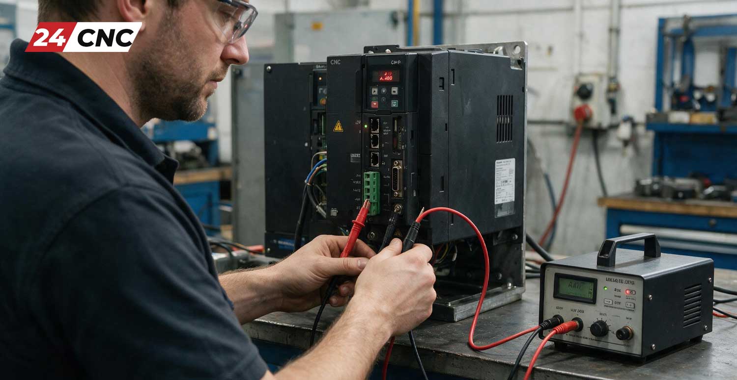
When operating high-performance industrial machinery, encountering an unexpected halt can bring your entire production schedule to a standstill. Among the most common and intimidating faults encountered by CNC operators and maintenance engineers is the A.400 Overvoltage Alarm. While this specific fault code is heavily associated with Yaskawa Sigma series servo drives, the underlying electromechanical principles—and the solutions—apply universally across almost all modern CNC servo systems.
The A.400 alarm is not merely a software glitch; it is a critical hardware protection mechanism. It indicates that the DC Bus voltage inside your servo amplifier has spiked beyond safe operational limits. If left unchecked, this excessive voltage can violently destroy the drive’s internal capacitors and IGBT modules, leading to catastrophic hardware failure and thousands of dollars in replacement costs.
In this comprehensive, 1500+ word pillar guide, we will dive deep into the electrical anatomy of the A.400 overvoltage fault. We will explore the mechanics of regenerative braking, identify the primary root causes of the alarm, and provide a masterclass on how to safely test your braking resistor using a multimeter. By the end of this guide, you will possess the specialized knowledge required to diagnose, repair, and prevent overvoltage alarms in your facility.
Understanding the A.400 Overvoltage Alarm and the DC Bus
To effectively fix the A.400 alarm, one must first understand how a CNC servo drive manages power. Modern AC servo drives operate by converting incoming AC power into DC power (rectification) and storing it in a capacitor bank known as the DC Bus. The drive then inverts this DC power back into precise, variable-frequency AC power to drive the servo motor.
However, an electric motor is a reversible machine. When the CNC controller commands a rapid deceleration—such as a heavy spindle coming to a stop or a massive gantry axis reversing direction—the kinetic energy of the moving mass forces the motor to act as a generator. This phenomenon is known as regeneration or Back-EMF (Electromotive Force).
The motor pumps this electrical energy back into the servo drive, causing the DC Bus voltage to rise rapidly. For example, a standard 200V class servo drive typically maintains a DC bus voltage of around 280VDC to 300VDC. If regenerative energy pushes this voltage above roughly 400VDC to 420VDC, the drive’s protective circuits instantly trip the A.400 Overvoltage Alarm to prevent the capacitors from exploding and the silicon components from burning out.
To learn more about how these complex drives function internally, refer to our beginner’s guide to CNC servo amplifiers and drives.
The Role of the Braking Resistor (Dynamic Braking)
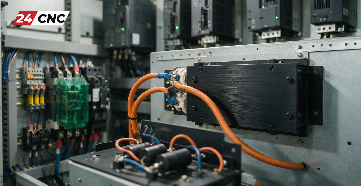
How do servo drives safely dispose of this massive influx of regenerative energy? They utilize a component known as a Braking Resistor (or Regeneration Resistor). When the drive detects that the DC bus voltage is climbing dangerously high, it activates an internal braking transistor (a chopper circuit). This transistor diverts the excess high-voltage DC current into the braking resistor.
The braking resistor acts exactly like an electrical sponge. It absorbs the electrical energy and converts it instantly into heat, safely dissipating it into the ambient air. Small servo drives often have internal braking resistors built directly into the chassis. However, larger drives moving heavy inertia loads require large, external braking resistors mounted in ventilated areas of the electrical cabinet.
When the braking resistor circuit fails, the drive has no way to bleed off the excess regenerative voltage. The result is an immediate A.400 overvoltage trip during deceleration.
Top 5 Causes of the A.400 Overvoltage Fault
Diagnosing an A.400 alarm requires a systematic approach. While the braking resistor is the usual suspect, several other factors can trigger this fault code. If you are experiencing CNC servo amplifier alarms, consider the following root causes:
1. A Failed or Burned-Out Braking Resistor
This is the most common culprit. Resistors endure extreme thermal stress. Over time, the internal resistive wire can burn out, break, and become an “open circuit.” When the drive attempts to send power to the broken resistor, no energy is dissipated, and the A.400 alarm triggers immediately upon deceleration.
2. Aggressive Deceleration Parameters
If your CNC program demands that a heavy axis stops too abruptly, the regenerative energy spikes faster than the resistor can burn it off. The physical load’s inertia simply overwhelms the braking capacity of the system. This often happens after a programmer optimizes a toolpath to run faster without adjusting the machine’s physical deceleration parameters.
3. Incoming Power Supply Surges
Overvoltage doesn’t exclusively come from the motor. If the utility power supplying your facility experiences a massive surge or a sustained high-voltage condition, the baseline DC bus voltage will be dangerously high before regeneration even occurs. Always verify the stability of your incoming power supplies using a True-RMS multimeter.
4. Disconnected or Damaged Wiring
In industrial environments, intense vibrations can loosen terminal screws. If the heavy-gauge wires connecting an external braking resistor to the drive’s terminals (usually labeled B1 and B2) vibrate loose or if the power cables are severed, the circuit is broken. The drive is perfectly fine, and the resistor is fine, but the energy cannot flow between them.
5. Internal Amplifier Hardware Failure
If the external resistor tests perfectly and the parameters are correct, the internal braking transistor (chopper) inside the amplifier and inverter unit may have failed. If this solid-state switch is blown open, it will never send power to the resistor. This unfortunately requires a complete replacement or component-level repair of the servo drive.
Deep Dive: How to Test a Braking Resistor with a Multimeter
Testing a braking resistor is a straightforward process, but it involves interacting with highly dangerous DC voltages. You must strictly adhere to electrical safety protocols before attempting this procedure.
Step 1: Secure the Machine and Discharge the Drive
Power down the main CNC breaker. Lock out and tag out (LOTO) the machine. Open the electrical cabinet and locate the drive throwing the A.400 alarm. Wait a minimum of 15 minutes. Using a multimeter set to VDC (Volts DC), carefully measure across the DC Bus terminals (usually marked as +, -, P, or N depending on the brand). Ensure the reading is below 10VDC before proceeding.
Step 2: Isolate the Braking Resistor
Locate the braking resistor terminals. On Yaskawa drives, these are typically marked B1 and B2. To get an accurate reading, you must completely disconnect at least one of the heavy power wires leading to the resistor. If you measure the resistor while it is still fully connected to the drive, you will measure the internal circuitry of the drive alongside the resistor, giving you a false reading.
Step 3: Measure the Ohmic Resistance
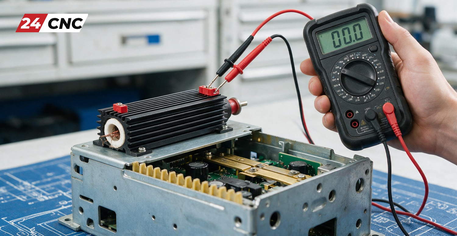
Set your multimeter to measure Resistance (Ohms / Ω). Place your probes firmly on the two terminals of the isolated braking resistor.
- Expected Reading: The resistor should display a specific Ohm value matching its nameplate rating. Common values range from 10 Ohms to 100 Ohms, depending on the drive’s wattage capacity. A variance of +/- 5% to 10% from the nameplate rating is generally acceptable.
- Fault Reading (Open): If the multimeter displays “OL” (Open Loop) or infinite resistance, the internal element is broken or burned completely through. The resistor is dead and must be replaced.
- Fault Reading (Shorted): If the multimeter reads 0 Ohms or very close to it (e.g., 0.1 Ohms), the resistor has short-circuited internally. Do not reconnect a shorted resistor! Doing so will cause a massive dead short across the DC bus the next time the drive brakes, instantly destroying the drive’s internal IGBTs.
Step 4: Check for Ground Faults
Keep your multimeter on the Resistance setting. Place one probe on a resistor terminal and the other probe firmly on the metal chassis of the machine (Earth Ground). The reading should be “OL” (infinite). If you read any resistance value (e.g., 500 Ohms, 1 Megaohm), the ceramic insulation inside the resistor has failed, and voltage is leaking to ground. This can cause erratic drive behavior and must be replaced.
How to Fix the A.400 Overvoltage Alarm: Actionable Solutions
Once you have diagnosed the root cause, you can implement one of the following solutions to clear the alarm and resume production.
- Replace the Faulty Resistor: If your multimeter test revealed an open or shorted resistor, replacing the unit is the only solution. Ensure you purchase a replacement with the exact same Ohmic value (Ω) and an equal or greater Wattage (W) rating.
- Increase Deceleration Time: If the resistor tests good, the mechanical load may simply be too much for the programmed stopping time. Access the drive parameters (e.g., via a Fanuc™ controller or Yaskawa keypad). Locate the “Deceleration Time” parameter and increase the value. Adding just a few hundred milliseconds to the decel ramp can drastically reduce the regenerative voltage spike without noticeably affecting cycle times.
- Verify Parameter Settings for External Resistors: If you recently upgraded a drive, ensure the parameter that defines the resistor type is correct. Many drives have an internal resistor connected by default via a jumper wire across terminals B2 and B3. If you remove this jumper to install an external resistor across B1 and B2, you must also change the software parameter to tell the drive to look for the external capacity. Failing to do this can trigger an A.400 or a related Regeneration Overload alarm.
- Check Incoming Line Voltage: Use a multimeter to test the AC voltage coming into the machine. If your facility power is running “hot” (e.g., reading 250VAC on a nominal 220VAC line), you are pushing the baseline DC bus voltage dangerously close to the A.400 trip threshold. You may need an isolation transformer to step down the facility power to the machine’s required specification.
Technical Comparison: Internal vs. External Braking Resistors
Understanding when to rely on a drive’s internal resistor versus upgrading to an external unit is crucial for optimizing CNC performance and preventing A.400 alarms in heavy-duty applications. Review the comparison table below.
Preventive Maintenance for CNC Braking Systems
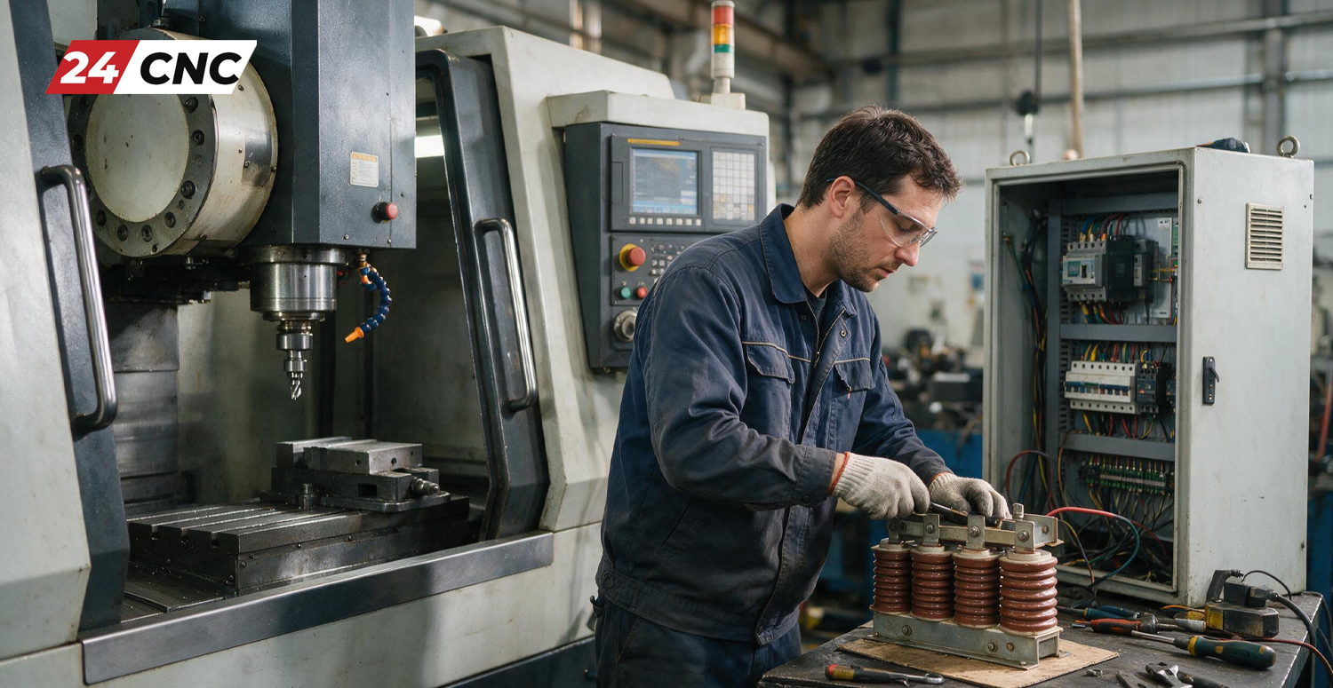
The best way to fix an A.400 alarm is to prevent it from happening in the first place. Incorporating the braking resistor into your daily, weekly, and monthly CNC machine maintenance checklist is highly recommended.
Because external braking resistors generate immense heat, they are prone to dust accumulation and wiring degradation. Regularly inspect the resistor housing for accumulated oil mist and metallic dust, which can create conductive bridges and cause arc faults. Ensure that the cabinet cooling fans are blowing adequately across the resistor fins. Finally, during scheduled downtime, use an insulated screwdriver to verify that the terminal connections on B1 and B2 remain tightly torqued, as thermal expansion and contraction can cause them to loosen over months of operation.
Frequently Asked Questions (FAQ)
Q: Can I completely disable the A.400 alarm in the parameters?
A: Absolutely not. The A.400 alarm is a critical hardware protection limit, not a flexible software warning. Disabling or bypassing this safety feature will result in the immediate and explosive destruction of the drive’s internal DC capacitors and IGBT modules the next time the motor decelerates.
Q: Can I run my CNC machine without a braking resistor attached?
A: In very rare cases with extremely slow, low-inertia applications (like a slow-moving conveyor), the internal capacitors alone might absorb the tiny regenerative energy. However, for 99% of CNC axis and spindle applications, removing the resistor will guarantee an A.400 fault every time the motor attempts to stop.
Q: My braking resistor gets extremely hot to the touch. Is it broken?
A: No, that means it is working exactly as designed! A braking resistor’s sole purpose is to convert excess electrical energy into heat. During heavy machining cycles, these resistors can easily exceed 150°C (300°F). This is why they must be mounted in well-ventilated areas away from sensitive control cables and plastics.
Is Your Servo Drive Beyond Repair?
If your braking resistor tests perfectly fine but the A.400 alarm persists, your servo amplifier’s internal chopper circuit has likely failed. Don’t let prolonged downtime eat into your profits.
Browse Replacement Servo Drives
Huge Inventory • Rapid Global Shipping • Expert Technical Support
Leave a comment
Your email address will not be published. Required fields are marked *