
In the highly precise ecosystem of CNC machining and industrial automation, smooth operation relies on absolute synchrony between mechanical hardware and electronic control systems. When you turn on your machine’s main power, you expect a ready state. However, few things are as frustrating for an operator or maintenance engineer as booting up the system only to be greeted by an immediate, hard-stop alarm before any axis movement even occurs. One of the most notorious and misunderstood of these faults is the A.050 Combination Error.
Most frequently encountered on Yaskawa Sigma II, Sigma V, and Sigma 7 series systems (though conceptually similar faults exist in other brands), the A.050 alarm indicates a critical identity crisis within your motion control hardware. Specifically, the servo amplifier and the servo motor are failing to recognize each other as a compatible pair, or the internal parameters dictating their relationship have been corrupted.
Because this error triggers immediately upon power-up, it completely disables the affected axis. Troubleshooting it requires a deep understanding of hardware matching, encoder communication, and servo parameter initialization. This extensive guide will break down the mechanics of the A.050 error, walk you through step-by-step diagnostic procedures, and explain how to properly configure your servo parameters to get your CNC machinery back online.
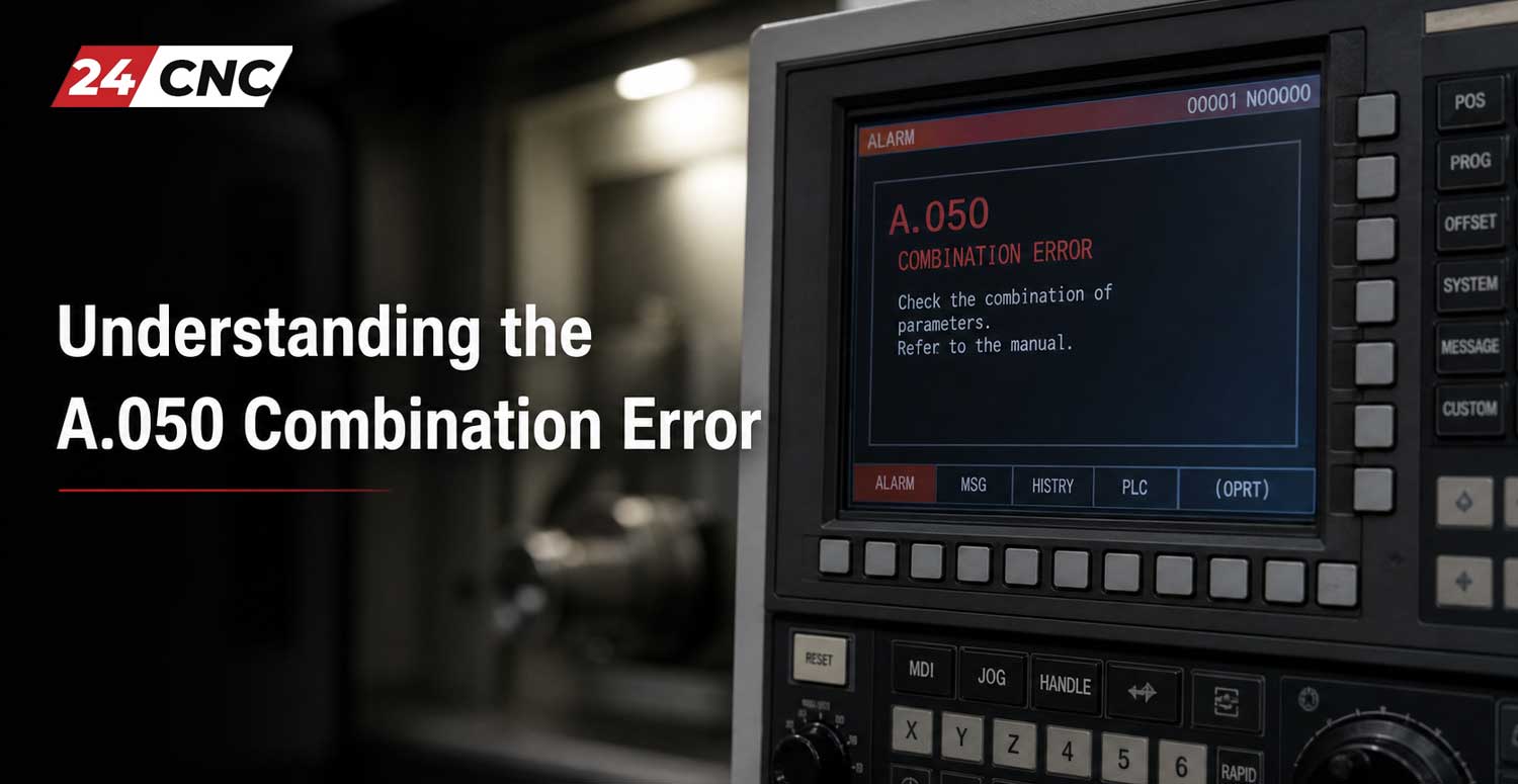
Understanding the A.050 Combination Error
To diagnose and troubleshoot CNC servo amplifier alarms effectively, you must understand what the amplifier is doing during its boot sequence. When control power is applied to a modern servo amplifier, it sends a handshake signal down the encoder cable to the connected servo motor.
The motor’s serial encoder replies with a packet of identifying data. This data includes the motor’s exact model number, its power rating (in Watts or Kilowatts), its maximum RPM, and its encoder resolution. The servo amplifier compares this received motor data against its own internal capacity rating and its programmed parameters.
The A.050 Combination Error is triggered when the amplifier’s microprocessor detects an irreconcilable mismatch during this handshake. The drive is essentially saying: “The motor I am connected to is either too large, too small, completely unrecognizable, or my internal parameters are telling me to expect a completely different motor type.”
This is a safety mechanism. If a 400W servo drive attempts to push optimal current into a 1.5kW motor, the drive will rapidly overheat and destroy its internal IGBT modules. Conversely, if a massive 3kW drive attempts to run a tiny 100W motor using default parameters, it could push too much current, melting the motor windings. The mathematical relationship governing this involves checking if the maximum current delivery aligns with the motor’s needs, often utilizing variations of the three-phase power formula: $P = V \times I \times \sqrt{3} \times \text{PF}$. If the $I$ (current) capacity of the drive does not match the motor’s required $I$, A.050 is thrown.
Primary Root Causes of Alarm A.050
While the error definition is straightforward, the actual cause in a real-world CNC environment can stem from several different hardware or software scenarios. Let’s explore the most common culprits.
1. Physical Hardware Capacity Mismatch
This is the most obvious cause, usually occurring right after a maintenance intervention or a machine rebuild. If a technician replaces a burned-out motor or a faulty drive, they must ensure the replacement part numbers are an exact match or an approved supersession. For example, connecting a Yaskawa SGDV-1R6A (400W capacity drive) to an SGMGV-09A (850W capacity motor) will instantaneously generate an A.050 combination error.
2. Faulty or Incorrect Rotary Encoder
Because the amplifier relies entirely on the rotary encoder to identify the motor, any failure in the encoder can trigger this alarm. If the encoder’s internal EEPROM chip (which stores the motor’s ID data) is corrupted due to an electrical surge, the drive will read garbage data upon boot and throw an A.050. Furthermore, replacing an absolute encoder with an incremental encoder without updating the corresponding servo parameters will also cause a combination mismatch.
3. Encoder Cable and Communication Issues
Industrial environments are harsh. The encoder cable running from the motor back to the cabinet is subjected to constant flexing, coolant exposure, and electromagnetic interference (EMI). If the data transmission lines (typically labeled PS and /PS, or Data+ and Data-) within the cable are severed or shorted, the ID handshake fails. While this sometimes causes a dedicated encoder communication error (like A.C90), a partial data loss during initial boot can manifest as an A.050.
4. Corrupted Servo Parameters
Sometimes, both the motor and the drive are perfectly healthy and perfectly matched, but the brain of the drive—its parameter set—has become scrambled. This can happen due to a dying internal battery, a severe power spike, or an operator accidentally writing incorrect values to the drive’s NVRAM (Non-Volatile Random Access Memory). If the parameter that defines the expected motor series (e.g., Pn000 or Pn00B) is altered, the drive thinks it’s looking at the wrong motor.
Step-by-Step Troubleshooting Procedure
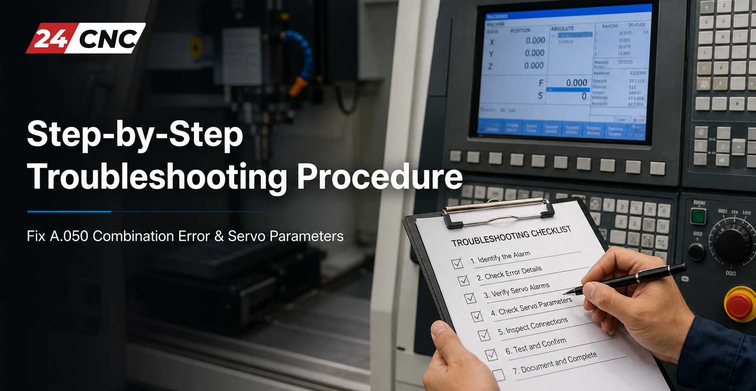
To resolve the A.050 error without wasting hours or replacing good parts, you must follow a highly structured, logical troubleshooting methodology. For an excellent primer on drive architectures before you begin, consider reviewing this beginner’s guide to CNC servo amplifiers and drives.
Step 1: The Nameplate Verification (The Sanity Check)
Before touching a single parameter or unbolting a motor, get a flashlight and read the nameplates on both the servo amplifier and the servo motor.
- Locate the Drive Model Number: Look at the side or front face of the servo drive. Write down the exact alphanumeric code (e.g., SGD7S-5R5A00A).
- Locate the Motor Model Number: Clean off the motor nameplate and write down its exact code (e.g., SGM7G-09AFC61).
- Cross-Reference the Manual: Open the manufacturer’s user manual (e.g., the Yaskawa Sigma-7 Hardware Manual) and navigate to the “Motor-Amplifier Combinations” table. Verify that the $5.5A$ drive is legally allowed to drive the $850W$ motor. If they are not listed as a pair, you have a hardware mismatch. You must procure the correct matching component.
Step 2: Inspecting the Encoder and Cables
If the hardware is definitively a matched pair, the problem lies in communication.
- Safely power down the machine and wait for the bus capacitors to discharge.
- Disconnect the encoder cable at the motor end and at the amplifier end (usually the CN2 connector).
- Inspect the pins for pushed-in contacts, corrosion from cutting fluids, or bent pins.
- Use a digital multimeter to perform a continuity check on all pins from end to end. Specifically, ensure the shield wire is continuous, as missing shielding can allow EMI to corrupt the boot handshake.
- If you have a known-good spare encoder cable, run it temporarily across the floor to bypass the machine’s cable tracks. If the A.050 clears, replace the machine’s internal cable.
Step 3: Initializing and Resetting Servo Parameters
If the hardware matches and the cables are verified, the most likely culprit is a corrupted parameter table. The most effective way to clear a software-induced A.050 is to perform a factory initialization of the servo parameters. Warning: Initializing parameters will wipe out custom tuning gains and I/O settings. Make sure you have a backup of the machine’s parameters before proceeding.
Here is the standard procedure for initializing parameters on a typical Yaskawa Sigma drive using the built-in digital operator (the LED screen and buttons on the front of the drive):
- Press the MODE/SET button until the display shows the utility function mode, starting with
Fn000. - Use the UP arrow button to scroll to function
Fn005(Initialize Parameters). - Press the DATA/SHIFT button for about 1 second to enter the initialization menu. The display will show
P.INIT. - Press and hold the MODE/SET button. The display will flash, indicating the parameters are being reset to factory defaults.
- Once the flashing stops and the screen reads
DONE, release the button. - Power down the main control power to the drive. Wait 10 seconds.
- Power the drive back up. The drive will now attempt a fresh handshake with the motor.
In many cases, clearing out corrupted logic via Fn005 forces the drive to accurately re-read the motor ID, instantly clearing the A.050 alarm.
Advanced Diagnostics Using PC Software
If the manual parameter reset fails, you may need deeper visibility. Using software like Yaskawa’s SigmaWin+ (connected via USB or serial to the drive) provides a direct window into the drive’s brain.
When you plug in with SigmaWin+, navigate to the Alarms tab. The software will often give a sub-code to the A.050 error. For example, it might specify “Encoder ID read failure” versus “Capacity mismatch.” Furthermore, you can use the software to view the exact motor ID string the drive thinks it is reading. If the string is a jumble of special characters, you know definitively that the encoder’s EEPROM is dead or the cable is severely shorted.
Technical Comparison: Parameter & Configuration Alarms
To avoid misdiagnosing your CNC fault, it is crucial to understand the differences between similar configuration alarms. The table below outlines the distinctions between the most common setup faults.
| Alarm Code | Fault Description | Primary Trigger | Standard Resolution |
|---|---|---|---|
| A.050 | Combination Error | Motor capacity and Amplifier capacity do not match; or encoder ID is unreadable. | Verify part numbers, check encoder cable continuity, initialize parameters (Fn005). |
| A.040 | Parameter Setting Error | A specific user parameter is set outside of its allowable range (e.g., electronic gear ratio is mathematically impossible). | Review recent parameter changes. Correct the out-of-bounds value in Pnxxx. |
| A.020 | Parameter Checksum Error | The internal memory (EEPROM) of the drive has failed or data is heavily corrupted. | Attempt Fn005 initialization. If alarm persists, the drive’s control board must be replaced. |
| A.C90 | Encoder Communications Error | Total loss of serial data between motor and drive. | Replace encoder cable or repair the motor’s encoder module. |
Preventative Maintenance & Best Practices
While the A.050 error is often an immediate roadblock, adopting strict maintenance routines can prevent it from recurring. First and foremost, document your machinery. Whenever a machine is commissioned, export a complete parameter backup using the manufacturer’s software and store it securely. Secondly, ensure that your heavily trafficked power cables and encoder cables are correctly routed in cable chains with proper bend radii. Mechanical stress on the cable jacket eventually leads to the microscopic wire fractures that disrupt encoder data and cause combination faults.
Frequently Asked Questions (FAQ)
Does a dead encoder battery cause an A.050 error?
Generally, no. A dead backup battery on an absolute encoder will trigger an Absolute Encoder Battery Alarm (such as A.810 or A.820). The battery only maintains the multi-turn positional data when power is off; it does not power the EEPROM that stores the motor ID. However, if a severe power spike destroyed the battery and the EEPROM simultaneously, an A.050 could occur alongside an A.810.
I initialized my parameters (Fn005) and the A.050 cleared, but now my axis moves in the wrong direction. Why?
Initializing the parameters wiped the drive back to its absolute factory state. This cleared the software corruption causing the A.050, but it also erased your machine-specific settings. You have lost your motor rotation direction parameter (usually Pn000.0), your electronic gear ratios, and your tuning gains. You must now reload your specific machine parameter backup to restore proper functionality.
Can I modify a parameter to force the drive to accept a mismatched motor?
No. The capacity limits are hardcoded into the drive’s firmware for safety and hardware protection. You cannot use a user parameter (like the Pn-series) to force a 200W drive to output enough current to safely control a 1.5kW motor. The hardware must fundamentally match.
Need the Exact Matching Servo Parts to Clear Your Alarm?
When dealing with an A.050 Combination Error, finding the perfect, verified hardware match is the only path forward. We stock a massive inventory of authentic, rigorously tested servo drives, motors, and OEM encoder cables ready for immediate dispatch.
Find Your Replacement Parts Now
Worldwide Shipping • Comprehensive Warranty • Expert Technical Support
Leave a comment
Your email address will not be published. Required fields are marked *