
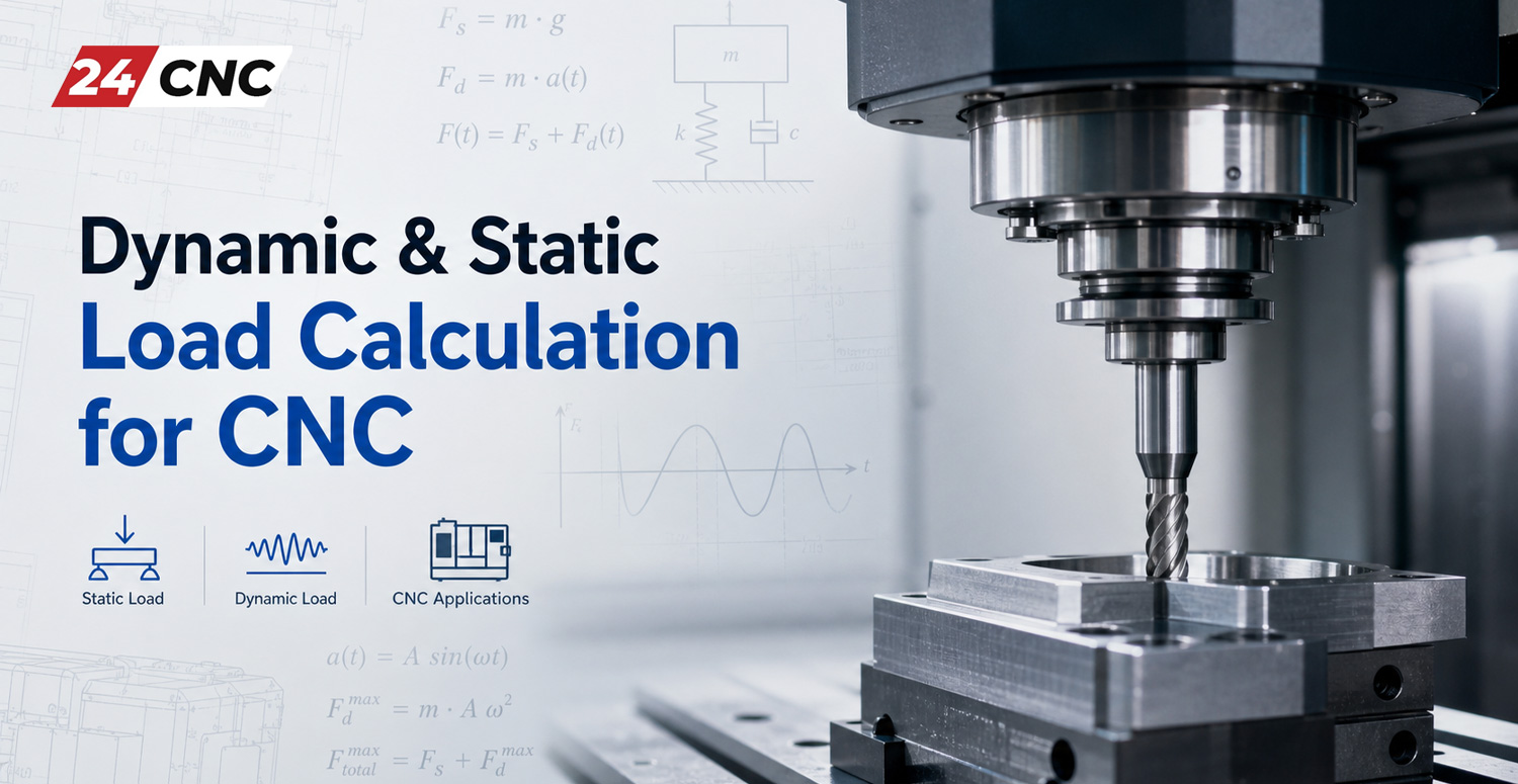
Designing, retrofitting, or troubleshooting a high-performance CNC machine requires a thorough mastery of mechanical force transmission. When an axis moves, accelerates, cuts material, and rapidly decelerates, every mechanical component—from the linear guideways to the drive screw and the feed servo—is subjected to complex, multi-directional stress. Failure to accurately compute these forces leads to premature fatigue, excessive deflection, loss of positional accuracy, or catastrophic mechanical breakdown.
Understanding dynamic and static load calculation for CNC systems is the cornerstone of machine tool engineering. Whether you are building a custom gantry router, selecting components for a high-speed vertical machining center (VMC), or replacing worn linear components, sizing elements based on their basic static load rating (C_0) and basic dynamic load rating (C) guarantees predictable operational life, high surface finish quality, and minimal downtime.
In this technical guide, we will analyze the physical principles of static and dynamic forces in CNC axes, derive the step-by-step mathematical formulas required by ISO standards, evaluate the impact of acceleration and cutting forces, and walk through a real-world calculation example.

Foundational Concepts: Static vs. Dynamic Load Ratings
Linear motion manufacturers (such as THK, HIWIN, NSK, and Bosch Rexroth) express the mechanical capacity of linear motion guides, ball screws, and support bearings using two primary metrics: Basic Static Load Rating (C_0) and Basic Dynamic Load Rating (C). While both values are measured in Newtons (\text{N}) or kilonewtons (\text{kN}), they govern completely different operational failure modes.
What is Static Load Rating (C_0)?
The static load rating (C_0) refers to the maximum stationary or low-speed load that a bearing or linear guide block can withstand without suffering permanent, unacceptable plastic deformation. When excessive force is applied to a stationary bearing, the rolling elements (balls or cylindrical rollers) press into the raceway surface. If this contact pressure exceeds the elastic limit of the material, it creates microscopic permanent indents—a failure phenomenon known as brinelling.
By international standard (ISO 14728-2 for linear bearings), the basic static load rating is defined as the static load that produces a permanent plastic deformation equal to 0.0001 times the diameter of the rolling element (0.01\% \cdot D_w) at the center of the most heavily stressed contact zone. Operating near or above this threshold introduces severe chatter, noise, and mechanical binding.
What is Dynamic Load Rating (C)?
The basic dynamic load rating (C) defines the constant load, unchanging in magnitude and direction, under which a group of identical linear motion bearings can achieve a theoretical nominal rating life (L_{10}) of 50\text{ km} (for JIS/Asian standards) or 100\text{ km} (for ISO/European standards) of linear travel without developing surface fatigue, spalling, or flaking on the raceways or rolling elements.
Dynamic load ratings assume continuous motion and cyclical stress. In CNC machinery, dynamic loading is almost always variable, depending on whether the machine is executing a rapid traverse (G00), a light finishing pass, or a heavy hogging cut (G01).
To ensure structural rigidity across different configurations, engineers often reference our breakdown on essential components of a CNC machine when architecting the mechanical kinematic chain.
Forces Acting on a CNC Axis: The Free-Body Diagram
Before entering numerical values into life equations, you must resolve the forces acting on the machine slide. In a typical CNC axis, total load is a superposition of four distinct force components:
- Gravitational Load (F_g): The weight of the carriage, table, fixtures, and the heaviest expected workpiece acting vertically downward:
F_g = m \cdot g
where m is the total mass in kilograms (\text{kg}) and g \approx 9.81\text{ m/s}^2. - Inertial Forces (F_a): Forces created during axis acceleration and deceleration:
F_a = m \cdot a
Modern high-speed CNC machines routinely accelerate at 0.5g to 1.5g (5\text{ m/s}^2 to 15\text{ m/s}^2). Under these rapid accelerations, the inertial force can drastically exceed the cutting force. - Cutting Forces (F_c): The reactive forces generated when the tool shears material. The cutting force is three-dimensional, comprising tangential cutting force (F_t), radial thrust force (F_r), and axial feed force (F_f). These loads act at the tool tip, creating massive overturning moment arms (M_x, M_y, M_z) about the linear guide blocks.
- Frictional Resistance (F_f): The drag of seals, wipers, and the rolling friction coefficient (\mu \approx 0.002 to 0.004 for linear ball guides; higher for box ways lined with Turcite).
The physical separation between the cutting tool tip and the center of the guide blocks creates moment loads:
- Pitching Moment (M_p or M_y): Rotation about the transverse horizontal axis.
- Yawing Moment (M_y or M_z): Rotation about the vertical axis during offset cuts.
- Rolling Moment (M_r or M_x): Rotation about the axis of travel.
Overturning moments must be mathematically converted into equivalent radial and reverse-radial forces distributed across the individual guide carriages before calculating the total bearing load.

Mathematical Formulations: Static Safety & Dynamic Life
Calculating the Static Safety Factor (f_s)
To prevent plastic deformation during worst-case conditions—such as sudden tool crashes, emergency stops, or severe vibration—the static safety factor (f_s) must be verified using the following formula:
f_s = \frac{C_0}{P_0}
Where:
- C_0 = Basic static load rating of the selected bearing/block (\text{N}).
- P_0 = Static equivalent load calculated under worst-case peak conditions (\text{N}).
Recommended minimum values for f_s in industrial CNC applications:
- Normal operation with low vibration: f_s \ge 1.5 – 2.0
- High-precision machine tools under normal cutting: f_s \ge 3.0 – 5.0
- Heavy-duty milling machines subject to severe shock/impact: f_s \ge 5.0 – 7.0
Calculating the Equivalent Dynamic Load (P_m)
Because a CNC axis experiences varying loads across a machining cycle (e.g., accelerating, rough cutting, finishing, decelerating, idling), you cannot use a single static number. Instead, calculate the mean dynamic equivalent load (P_m) using the cubic mean formula:
P_m = \sqrt[p]{\frac{P_1^p \cdot v_1 \cdot t_1 + P_2^p \cdot v_2 \cdot t_2 + \dots + P_n^p \cdot v_n \cdot t_n}{v_1 \cdot t_1 + v_2 \cdot t_2 + \dots + v_n \cdot t_n}}
Where:
- P_n = Equivalent load during step n (\text{N})
- v_n = Travel velocity during step n (\text{m/min})
- t_n = Operational time ratio of step n (\%)
- p = Load-life exponent (p = 3 for ball bearings; p = \frac{10}{3} \approx 3.333 for roller bearings)
Nominal Service Life Calculation (L_{10})
Once P_m is determined, calculate the nominal fatigue life (L) in kilometers of travel:
L = \left( \frac{f_H \cdot f_T \cdot f_C \cdot C}{f_w \cdot P_m} \right)^p \times 50\text{ km}
Where the correction coefficients account for real-world environmental and operational variables:
- f_H = Hardness factor: 1.0 if the raceway hardness is \ge 58\text{ HRC}; drops drastically below this hardness.
- f_T = Temperature factor: 1.0 for operational environments below 100^\circ\text{C}.
- f_C = Contact factor: Accounts for load distribution when blocks are mounted in close proximity (0.81 for 2 blocks touching).
- f_w = Load/vibration coefficient:
- Smooth motion without impact (v \le 15\text{ m/min}): f_w = 1.0 – 1.2
- Normal motion with moderate acceleration (15 < v \le 60\text{ m/min}): f_w = 1.2 – 1.5
- High-speed motion with aggressive shock/impact (v > 60\text{ m/min}): f_w = 1.5 – 2.5
To convert travel distance into service life hours (L_h):
L_h = \frac{L \times 10^6}{2 \cdot S \cdot n_c \cdot 60}
Where S is stroke length in millimeters (\text{mm}) and n_c is reciprocating cycles per minute.
The Crucial Role of Preload in Dynamic Calculations
In high-precision CNC machine tools, zero-backlash operation is mandatory. Bearings and ball screws are intentionally preloaded with internal interference to eliminate clearance and enhance mechanical stiffness.
However, preload represents an internal continuous mechanical load. When calculating dynamic load, you must consider whether the applied external load relieves or intensifies the preload. If you are configuring a high-rigidity setup, reviewing how to choose linear guide preload correctly is critical. Excessive preload increases rolling resistance, generates frictional heat, and reduces the L_{10} service life, whereas inadequate preload leads to axis deflection and tool chatter.
Furthermore, when selecting rail architectures for heavy cutting operations, comparing roller vs ball linear guides for heavy CNC is essential. Roller guides provide line contact rather than point contact, resulting in a significantly higher static load rating (C_0) and higher dynamic rigidity under identical envelope dimensions.
Technical Comparison: Static vs. Dynamic Load Parameters
To visualize how these two metrics dictate machine design decisions, review the comparative breakdown below:
| Parameter | Static Load Calculation (C_0, P_0) | Dynamic Load Calculation (C, P_m) |
|---|---|---|
| Governing Phenomenon | Permanent raceway plastic deformation (Brinelling) | Subsurface rolling contact fatigue (Spalling/Flaking) |
| Primary Engineering Metric | Static Safety Factor: f_s = \frac{C_0}{P_0} | Nominal Life: L_{10} = \left(\frac{C}{P_m \cdot f_w}\right)^p \times 50\text{ km} |
| Critical Axis Conditions | E-stops, physical crashes, high clamping loads, stationary holds | Continuous duty cycles, G00 rapids, high-feed roughing |
| Sensitivity to Speed | Independent of velocity (v = 0 or micro-creep) | Highly sensitive; dynamic effects scale via f_w and duty time |
| Failure Consequence | Immediate surface divots, non-recoverable axis chatter, rough motion | Progressive pitting, increased thermal drift, gradual backlash |
| Typical Target Design Limits | f_s \ge 3.0 for standard CNC; f_s \ge 5.0 for heavy milling | > 20,000 to 50,000 operating hours under standard duty cycles |

Practical Step-by-Step Calculation Walkthrough
To demonstrate the calculation process in a real-world scenario, let us evaluate the X-axis linear guide system for a CNC milling machine under typical production parameters.
Machine Parameters & Operating Profile
- Total moving mass (table + fixture + workpiece): m = 400\text{ kg}
- Total gravitational force: F_g = 400 \times 9.81 = 3924\text{ N}
- Guide configuration: 2 rails with 2 carriages per rail (4 carriages total)
- Maximum acceleration: a = 5\text{ m/s}^2 (\approx 0.51g)
- Cutting force along travel axis: F_c = 2500\text{ N}
- Candidate guide block: Size 25 Ball Linear Guide (C = 25.2\text{ kN} = 25,200\text{ N}; C_0 = 41.5\text{ kN} = 41,500\text{ N})
- Load exponent: p = 3 (ball type)
- Service factor: f_w = 1.4 (medium shock / dynamic milling)
Step 1: Calculate Load Distribution per Carriage
Assuming symmetrical positioning, gravitational force distributes evenly across the 4 carriages:
P_{\text{static, grav}} = \frac{3924\text{ N}}{4} = 981\text{ N}
Step 2: Peak Acceleration & Static Verification
During maximum acceleration, the inertial force is:
F_a = 400\text{ kg} \times 5\text{ m/s}^2 = 2000\text{ N}
Under a worst-case scenario (sudden e-stop while taking a heavy cut), peak static equivalent load (P_0) on the most heavily loaded carriage combines gravity, inertial shock, and cutting thrust moments (calculated via spatial coordinate vectors, producing a localized peak reaction load of P_{\max} \approx 6200\text{ N}):
f_s = \frac{C_0}{P_0} = \frac{41500\text{ N}}{6200\text{ N}} \approx 6.69
Since f_s = 6.69 > 5.0, the static safety factor is well within safe operating margins against plastic brinelling.
Step 3: Mean Dynamic Equivalent Load (P_m)
Assume the machining cycle consists of three steps:
- Phase 1: Rapid positioning (G00): Load on critical block P_1 = 1600\text{ N}, velocity v_1 = 30\text{ m/min}, time share t_1 = 20\%
- Phase 2: Rough cutting (G01): Load on critical block P_2 = 3800\text{ N}, velocity v_2 = 3\text{ m/min}, time share t_2 = 60\%
- Phase 3: Fine finishing: Load on critical block P_3 = 1200\text{ N}, velocity v_3 = 6\text{ m/min}, time share t_3 = 20\%
Compute distance-weighted velocity-time factors:
- v_1 \cdot t_1 = 30 \times 0.20 = 6.0
- v_2 \cdot t_2 = 3 \times 0.60 = 1.8
- v_3 \cdot t_3 = 6 \times 0.20 = 1.2
- \sum (v_i \cdot t_i) = 6.0 + 1.8 + 1.2 = 9.0
Now calculate the mean dynamic equivalent load P_m:
P_m = \sqrt[3]{\frac{(1600^3 \times 6.0) + (3800^3 \times 1.8) + (1200^3 \times 1.2)}{9.0}}
P_m = \sqrt[3]{\frac{(4.096 \times 10^9 \times 6.0) + (5.487 \times 10^{10} \times 1.8) + (1.728 \times 10^9 \times 1.2)}{9.0}}
P_m = \sqrt[3]{\frac{2.457 \times 10^{10} + 9.877 \times 10^{10} + 2.073 \times 10^9}{9.0}} = \sqrt[3]{\frac{1.254 \times 10^{11}}{9.0}} \approx \sqrt[3]{1.393 \times 10^{10}} \approx 2406\text{ N}
Step 4: Calculate Nominal Service Life
Assuming hardened guide rails (f_H = 1.0), normal temperature (f_T = 1.0), single-carriage spacing (f_C = 1.0), and f_w = 1.4:
L = \left( \frac{1.0 \times 25200}{1.4 \times 2406} \right)^3 \times 50\text{ km} = \left( \frac{25200}{3368.4} \right)^3 \times 50\text{ km} \approx (7.48)^3 \times 50 \approx 418.5 \times 50 \approx 20,925\text{ km}
If the machine traverses an average linear distance of 8\text{ km} per working day, operating 250 days per year (2000\text{ km/year}):
\text{Life in Years} = \frac{20925\text{ km}}{2000\text{ km/year}} \approx 10.46\text{ years}
This verification confirms that the selected guide size provides adequate rigidity and a service life exceeding a decade under continuous production conditions.
Translating Linear Load Calculations to Drive Sizing
Load calculation does not stop at linear guides; the resulting dynamic and static forces directly determine the requirements for drive components such as the ball screw and the servo motor:
- Ball Screw Buckling & Life: High dynamic loads dictate the required core diameter of the screw shaft to prevent column buckling under axial compression. When ordering screws, you must also select the proper accuracy level; see our breakdown on C3, C5, and C7 ball screw precision grades to balance pitch accuracy with budget.
- Servo Torque Sizing: Total dynamic axial force (F_{\text{axial}}) converts directly to motor drive torque (T_a) through screw lead (P_b) and transmission efficiency (\eta):
T_a = \frac{F_{\text{axial}} \cdot P_b}{2\pi \cdot \eta}
Selecting an undersized motor causes tracking errors, while an oversized motor increases rotor inertia. Explore our guide on servo motors and CNC servo amplifiers and drives to properly match drive torque to axis inertia. - Coupled Spindle Effects: Cutting forces acting on the feed axis originate at the spindle nose. Understanding how power is distributed between axes is critical, as detailed in our analysis of spindle drives vs. servo drives.
Frequently Asked Questions (FAQ)
1. Why do linear guides often fail long before their theoretical L_{10} calculated life?
The theoretical L_{10} equation assumes ideal conditions: pure elastohydrodynamic lubrication, zero contamination, and perfect mounting alignment. In real CNC machine shops, linear guides fail prematurely due to three main factors: ingress of fine swarf or abrasive dust that damages scraper seals, loss of lubricating oil/grease, and mounting rail parallelism errors that introduce unintended internal twisting loads.
2. What is the difference between European (ISO) and Japanese (JIS) dynamic ratings?
JIS (Japanese Industrial Standard) dynamic load ratings (C) are rated for a nominal travel life of 50\text{ km}, whereas ISO/DIN (European) standards rate dynamic life at 100\text{ km}. Because nominal life scales to the third power for balls (L \propto C^3), you cannot directly compare numerical values without converting them. To convert a 50\text{ km} JIS rating to a 100\text{ km} ISO rating, divide by approximately 1.26 for ball guides (C_{100\text{km}} \approx \frac{C_{50\text{km}}}{1.26}).
3. How does high acceleration affect static vs. dynamic calculations?
High acceleration dramatically impacts both calculations. For static safety, peak acceleration (F = m \cdot a) adds an instantaneous force vector that can spike moment loads on rear carriages, requiring a higher static safety factor (f_s \ge 5.0). For dynamic life, rapid acceleration increases the load during positioning phases (P_1), raising the cubic mean equivalent load (P_m) and necessitating a higher service factor (f_w = 1.5 – 2.0), which lowers the calculated operational hours.
4. Can I use static load calculation alone to design a CNC machine?
No. Sizing purely based on static load will almost always result in an undersized, flexible machine. Static calculations only protect against plastic deformation when stationary. CNC machines require extreme dynamic stiffness under varying cutting forces to prevent tool deflection, chatter marks, and fatigue failure. Both static safety (f_s) and dynamic travel life (L_{10}) must be verified.
Summary & Engineering Best Practices
Accurate dynamic and static load calculation transforms CNC axis design from guesswork into predictable mechanical science. To summarize best practices when engineering or retrofitting a machine tool:
- Always account for 3D cutting moment arms: Never assume the cutting load acts in line with the carriage centers. Overturning moments (M_p, M_y, M_r) create severe localized forces on individual blocks.
- Verify the static safety factor (f_s \ge 3 – 5): Ensure emergency stops or tool plunge shocks will not cause brinelling damage to precision ground raceways.
- Standardize calculation units: Verify whether supplier catalog ratings are calculated at 50\text{ km} or 100\text{ km} before comparing specifications.
- Account for preload and environment: Use appropriate vibration factors (f_w) and maintain consistent lubrication to match theoretical calculations with real-world operating lifespans.
Source High-Precision Linear Motion & CNC Components
Need help selecting the correct linear guides, ball screws, or servo motors for your CNC machine? Get premium, industrial-grade automation hardware backed by technical expertise and global support.
Leave a comment
Your email address will not be published. Required fields are marked *