
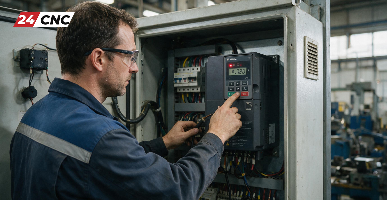
Encountering an A.720 alarm on your Yaskawa SERVOPACK can bring high-precision manufacturing to a sudden, costly standstill. Defined in Yaskawa technical documentation as a Motor Overload (Continuous) Alarm, the A.720 fault indicates that the servo drive has detected continuous current drawing above the maximum rated capacity of the connected motor for a sustained period. This safety mechanism triggers to prevent irreversible thermal damage to the servo motor windings, internal drive power electronics, and mechanical drive components.
Whether you are running a multi-axis CNC milling machine, a high-speed turning center, or automated robotic systems driven by Yaskawa Sigma-II, Sigma-III, Sigma-V, or Sigma-7 series drives, understanding how to systematically diagnose an A.720 fault is critical. This comprehensive troubleshooting guide covers the primary root causes of the A.720 overload code, provides step-by-step diagnostic workflows, details key drive parameters, and offers actionable repair strategies to get your machine safely back online.
Understanding the Yaskawa A.720 Overload Alarm Mechanism
Unlike instantaneous overcurrent faults—such as the Yaskawa A.710 overcurrent alarm, which trips in milliseconds due to direct short circuits or power stage breakdowns—the A.720 alarm operates on an I²t thermal accumulation counter. The SERVOPACK continuously measures the effective output current supplied to the motor over time.
When the motor operates within its rated continuous torque output, thermal energy dissipates safely. However, if the operational load demands torque exceeding 100% of the motor’s rated capacity continuously, heat accumulates in the stator windings. Once the drive’s internal algorithm calculates that the accumulated thermal energy has reached a critical threshold, it trips the A.720 alarm to prevent winding insulation failure and rotor demagnetization.
A.710 vs. A.720 vs. A.710/A.740 Comparison:
- A.710 (Instantaneous Overcurrent): Immediate trip caused by hardware short circuits, grounded motor leads, or failed IGBT modules.
- A.720 (Motor Overload – Continuous): Time-delayed trip caused by sustained excessive torque, mechanical binding, or incorrect motor parameters.
- A.740 (Lock Alarm): Triggered when the motor shaft is completely stationary while maximum current is applied (stalled motor).
Primary Causes of the Yaskawa A.720 Alarm
Isolating an A.720 fault requires evaluating three primary areas: mechanical infrastructure, electrical wiring/cabling, and drive configuration. Below are the most common root causes encountered in field service:
1. Mechanical Binding and Excessive Axis Load
Physical obstruction along the CNC axis is the most frequent trigger for an A.720 code. Over time, components wear down, leading to mechanical resistance that forces the servo motor to output near-maximum continuous current just to maintain programmed positioning. Key culprits include:
- Worn or unlubricated ball screws, linear guide blocks, and support bearings.
- Degraded slideway surfaces or improper gib adjustments on box-way machines.
- Mechanical collisions, axis crashes, or chips wedged within covers and ball screw nuts.
- Failed holding brakes that remain partially or fully engaged while the motor is commanded to move.
2. Electrical Wiring and Phase Disconnection
Disruptions in power transmission force the drive to output uneven current, rapidly overheating the motor windings:
- Loose, oxidized, or damaged conductors in the power cable (U, V, W phases).
- Single-phasing conditions where one phase wire breaks or disconnects at the engine-side connector or drive terminal block.
- Intermittent high resistance in cable lines caused by continuous bending inside cable tracks.
3. Encoder Feedback Issues & Signal Noise
The SERVOPACK relies on precise position feedback to calculate rotor position and current timing. If the rotary encoder yields erratic signals, the drive may apply misaligned phase currents, leading to excessive current draw without productive motion.
- Damaged or unshielded encoder cables picking up EMI/RFI noise from nearby lines.
- Optical disk contamination or loose feedback couplings within the encoder housing. Review our guide on troubleshooting inaccurate rotary encoder readings for additional feedback diagnostics.
4. Incorrect Parameter Setup or Tuning Instability
If the SERVOPACK was recently replaced or reconfigured, improper settings can trigger false overload alarms:
- Mismatched motor-drive combination or incorrect motor code parameter set in the SERVOPACK.
- Overly aggressive gain settings (high speed/position loop gains) inducing high-frequency mechanical oscillation or hunting.
- Excessive acceleration/deceleration rates programmed beyond the motor’s physical torque envelope.
5. SERVOPACK Power Electronics Failure
In rarer cases, internal failure within the drive’s power stage cause inaccurate current sensing. Degraded current feedback sensors or failing IGBT modules can lead the drive controller to register an artificially high current draw. For general drive diagnostic techniques, refer to our article on diagnosing CNC servo amplifier alarms.
Step-by-Step Diagnostic & Troubleshooting Procedure
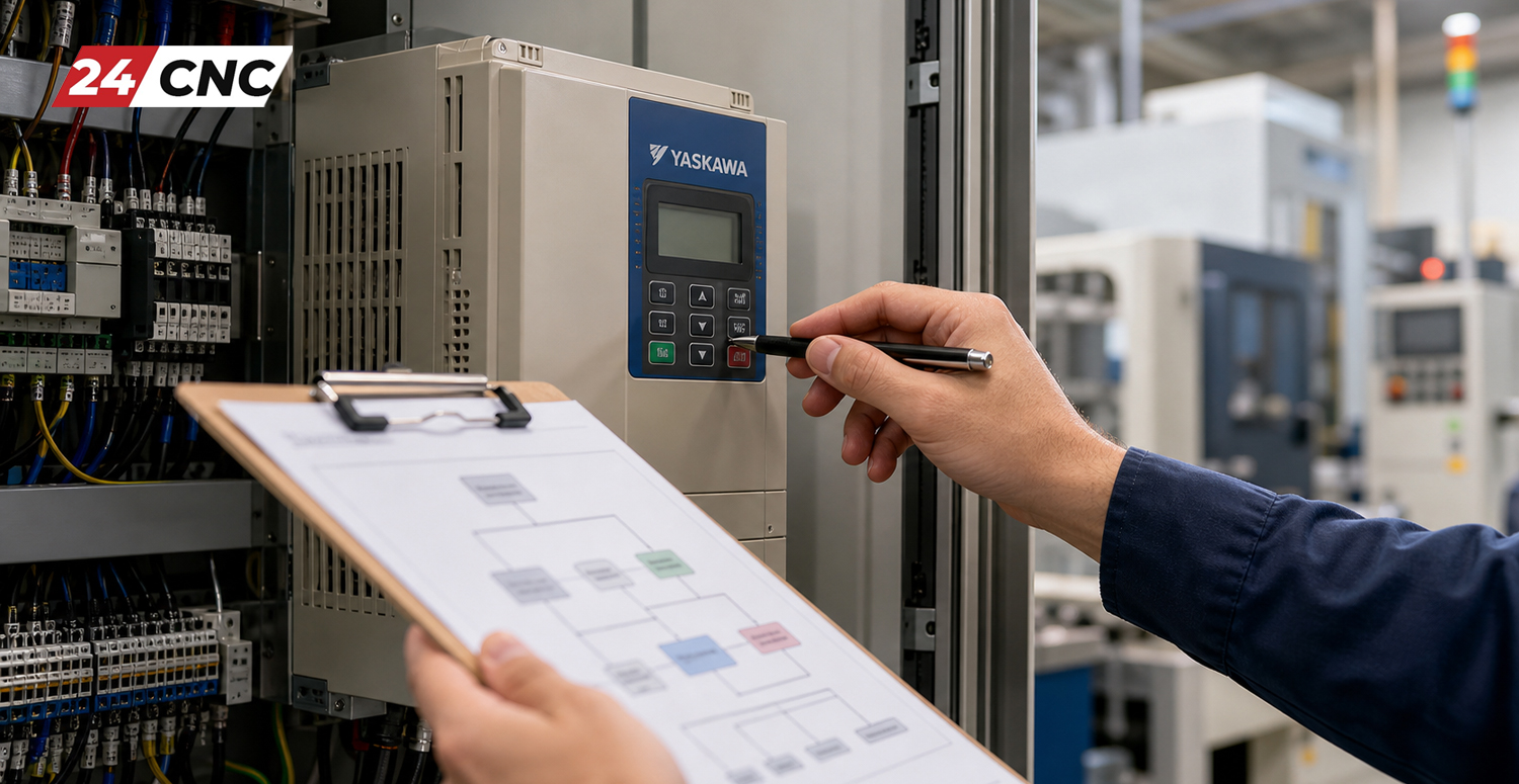
Follow this systematic workflow to isolate and fix the root cause of the Yaskawa A.720 alarm. Always observe lockout/tagout (LOTO) protocols before performing physical or electrical work.
- Step 1: Perform a Physical & Mechanical Inspection
Disconnect power, decouple the servo motor shaft from the ball screw or gearbox, and manually rotate the axis mechanism (using a manual handwheel or by turning the ball screw by hand). Check for binding, tight spots, or noise along the entire travel path. Verify slide lubrication and inspect way covers.
- Step 2: Inspect Motor Holding Brake Operation
If the axis features an integrated electromagnetic brake (commonly found on vertical Z-axes), verify that 24V DC is supplied to the brake coil when the servo is enabled. A failed brake rectifier or broken wire will keep the brake engaged, causing immediate overload when the motor attempts to move.
- Step 3: Test Motor Power Winding Resistance
Disconnect the motor power plug from the SERVOPACK (U, V, W terminals). Use a calibrated digital multimeter to measure resistance across phases (U-V, V-W, W-U). Resistance values must be balanced across all three combinations (typically well below 10 Ohms depending on motor frame size). Next, check insulation resistance from each phase terminal to ground using a 500V megohmmeter (Megger). Any reading below 10 MΩ indicates breakdown in the motor windings or motor cable.
- Step 4: Check Cables, Connectors & Terminals
Inspect all power connections at both the SERVOPACK terminals and the motor junction box. Look for signs of overheating, charred insulation, loose terminal screws, or pin corrosion inside drive-side connectors.
- Step 5: Monitor Real-Time Current via SigmaWin+ Software
Connect Yaskawa’s SigmaWin+ engineering software to the drive via the CN7 USB/serial interface. Monitor the Un002 (Effective Current Ratio) monitor display during operation. Standard continuous operation should remain comfortably below 80–90%. If the value steadily climbs to 100%+ under steady-state jog conditions, the load is mechanically excessive.
- Step 6: Verify Servo Parameters and Autotuning Settings
Check parameter settings against machine documentation. Ensure torque limits (e.g., Pn402, Pn403 in Sigma-V) are configured correctly and that autotuning parameters match system inertia. Reset gains if the motor is vibrating or screaming during motion.
Technical Diagnostic Matrix: Yaskawa A.720 Fault Symptoms & Solutions
Use the following reference matrix to quick-match observed symptoms to root causes and corrective actions:
| Symptom | Primary Suspect | Diagnostic Method | Corrective Action |
|---|---|---|---|
| Alarm occurs immediately upon Servo ON command | Engaged Brake / Phase Loss / Shorted Cable | Verify brake 24V supply; check phase continuity U/V/W. | Replace brake relay or repair broken motor power cable. |
| Alarm trips after 5–15 minutes of continuous running | Mechanical Overload / Friction / Thermal Accumulation | Monitor Un002 current ratio in SigmaWin+; feel for component heat. | Lubricate ways, check ball screw pre-load, rebuild axis assembly. |
| Alarm occurs only during high-speed acceleration/deceleration | Accel/Decel Rates / Gain Instability / Low Torque Limit | Review Pn401/Pn402 settings; log torque response traces. | Extend ramp times in CNC controller; re-run drive autotuning. |
| Motor hums violently or vibrates before tripping A.720 | High Loop Gains / Encoder Noise / Loose Coupling | Inspect encoder cable shielding; check mechanical shaft coupling. | Lower velocity gain Pn100/Pn101; replace noise-damaged encoder cable. |
| Alarm occurs uncoupled from mechanical load | Damaged SERVOPACK Current Sensor / Internal IGBT | Run motor uncoupled in jog mode via SigmaWin+. If current reads 100%+, drive is faulty. | Repair or replace SERVOPACK amplifier unit. |
Preventive Maintenance & Parameter Audit
Preventing recurring A.720 overload alarms requires combining structured preventive maintenance with regular parameter audits. Incorporate these tasks into your facility’s maintenance schedule:
- Execute Daily & Weekly Maintenance Checklists: Clean and lubricate axis ways, verify automatic lubrication pump pressure, and listen for grinding bearings. Review our complete CNC machine maintenance checklist for guided protocols.
- Inspect Heat Dissipation Components: Check that cooling fans on both the servo motor housing and the SERVOPACK heatsink are spinning freely and clear of dust buildup. Overheating drive electronics lower thermal trip thresholds. If drive fans fail, source replacement drive controller fans promptly.
- Audit Important Parameters in SigmaWin+:
- Pn52B / Pn52C: Overload warning and alarm detection levels. Ensure these remain at OEM factory default unless instructed by Yaskawa engineering.
- Pn000 / Pn002: Control mode selection and basic function parameters. Verify correct encoder type and motor code match.
Frequently Asked Questions (FAQ)
Q: Can I simply clear or reset the A.720 alarm and continue running?
A: While cycling drive power or executing an alarm reset command via the CNC controller will clear the A.720 code temporarily, doing so without resolving the root cause risks destroying the motor windings or drive power modules. The alarm indicates real thermal accumulation. Repeatedly resetting the fault under load can cause irreversible thermal breakdown.
Q: What is the difference between Yaskawa A.710 and A.720 alarms?
A: A.710 is an Instantaneous Overcurrent Alarm triggered immediately when output current spikes well past maximum limits (usually caused by direct electrical short circuits or blown IGBT power modules). A.720 is a Continuous Motor Overload Alarm triggered over a time period when current remains continuously elevated above rated output due to mechanical friction or excessive load.
Q: How can I tell if the A.720 alarm is caused by the motor or the SERVOPACK?
A: Uncouple the motor shaft mechanically from the machine load and attempt to jog the motor. If the motor runs smoothly and current monitor parameter Un002 remains low (<20%), the issue lies in machine mechanics. If the A.720 alarm occurs even with an uncoupled motor and tested cables, the issue points to damaged internal current sensors in the SERVOPACK amplifier or internal motor shorting.
Q: Where can I source replacement Yaskawa drives, motors, and cables?
A: High-quality, fully tested replacement components—including Yaskawa SERVOPACKs, servo motors, encoder cables, and power wiring—are available directly from trusted CNC parts suppliers online at 24cnc.com.
Need Replacement Yaskawa Servos or Fast Technical Support?
Don’t let drive alarms slow down your production lines. 24cnc.com stocks a massive inventory of tested Yaskawa SERVOPACKs, servo motors, encoder cables, and industrial automation spare parts ready for immediate global dispatch.
Shop Genuine Yaskawa Parts Now
Fast Global Shipping • Rigorously Tested Components • Expert CNC Automation Support
Leave a comment
Your email address will not be published. Required fields are marked *