
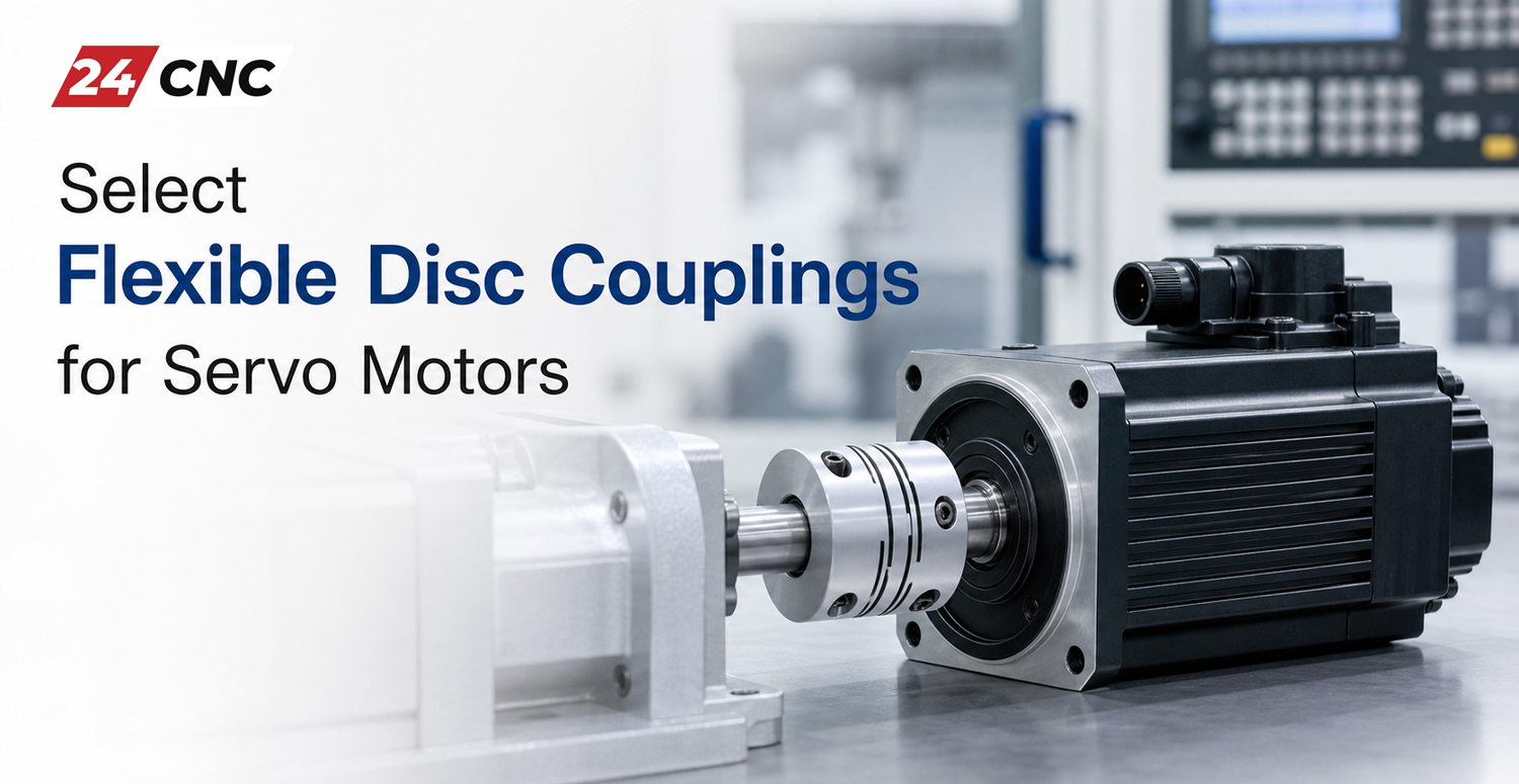
In the highly demanding world of industrial automation and precision CNC machining, the connection between a servo motor and its driven load—typically a ball screw or a high-speed spindle—is a critical point of failure or success. You can invest heavily in a top-tier controller, a high-resolution absolute encoder, and a premium servo drive, but if you do not properly select flexible disc couplings for servo motors, the entire system’s accuracy will degrade. The coupling acts as the mechanical bridge transferring rotational torque while compensating for inevitable alignment errors. In servo-driven systems where positioning down to the micron is required, a standard coupling will not suffice.
Flexible disc couplings have emerged as the gold standard for high-performance servo applications. Unlike standard jaw couplings or rigid sleeves, disc couplings are engineered to provide absolute zero backlash, immense torsional stiffness, and low inertia, all while gracefully absorbing angular, parallel, and axial misalignments. This comprehensive guide will walk you through the technical principles, selection criteria, and installation best practices to ensure your CNC machinery operates at peak precision.
What is a Flexible Disc Coupling?
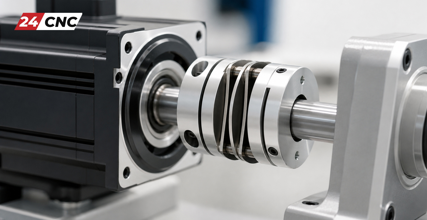
A flexible disc coupling (often referred to as a disk coupling) is a type of mechanical power transmission component designed to transmit torque from a driving shaft to a driven shaft while accommodating misalignment. It achieves this flexibility through thin, metallic discs or disc packs (usually made of high-grade stainless steel) bolted alternately to the driving and driven hubs.
There are generally two types of disc couplings used in automation:
- Single Disc Couplings: These utilize a single pack of metallic discs. They are exceptionally stiff torsionally but can primarily only accommodate angular misalignment and a very limited amount of axial play. They cannot effectively compensate for parallel (radial) misalignment.
- Double Disc Couplings: These feature two disc packs separated by a center spacer. This dual-flexing action allows the coupling to easily absorb angular, axial, and crucially, parallel misalignment, making them the preferred choice for most CNC servo motor applications where perfect alignment is virtually impossible to maintain over the machine’s lifespan.
Why CNC Servo Motors Demand Specialized Couplings
To understand how to select flexible disc couplings for servo motors, we must first look at the unique operational characteristics of these motors. Whether you are running a high-torque Fanuc™ servo motor or a highly dynamic Mitsubishi servo motor, the demands placed on the power transmission components are extreme.
The Absolute Necessity of Zero Backlash
Backlash is the amount of clearance or “play” between mating components. In a CNC machine, if the motor shaft turns 0.01 degrees, the ball screw must turn exactly 0.01 degrees instantaneously. If the coupling introduces any mechanical play, there will be a delay in movement when reversing direction. This results in positioning errors, poor surface finishes, and out-of-round circular interpolations. While advanced CNC controllers allow you to fix and compensate for CNC axis backlash electronically, software cannot fully correct the dynamic instability caused by a sloppy coupling. Flexible disc couplings, due to their bolted metallic disc design, inherently operate with zero backlash.
Maximizing Torsional Stiffness
Servo systems are highly dynamic. They rapidly accelerate, decelerate, and reverse direction thousands of times per hour. Torsional stiffness refers to a coupling’s resistance to twisting under a load. If a coupling has low torsional stiffness (like an elastomer jaw coupling), it acts like a spring. When the servo motor abruptly stops, the “spring” unwinds, causing the driven load to vibrate or oscillate. This forces the servo amplifier to continuously hunt for the target position, leading to servo instability, resonance, and potential overcurrent alarms. Disc couplings provide exceptionally high torsional stiffness, ensuring crisp, immediate transfer of motion and preserving the high-frequency response of the servo loop.
Low Mass Moment of Inertia
To achieve high-speed positioning, the rotational mass (inertia) of the moving parts must be minimized. A coupling that is too heavy will consume a significant portion of the motor’s torque just to accelerate itself, leaving less power for the actual cutting or moving operation. Disc couplings are typically constructed from high-strength, lightweight aluminum alloy hubs with thin stainless steel discs, keeping the moment of inertia remarkably low.

Critical Factors to Consider When Selecting a Disc Coupling
When looking at an engineering catalog, you will face dozens of specifications. Here is how to navigate the selection process for your specific machine tool application.
1. Continuous and Peak Torque Capacity
The coupling must be able to transmit the continuous rated torque of the servo motor, but more importantly, it must handle the peak (maximum) torque. Servo motors can typically output up to 300% of their rated torque for short durations during rapid acceleration or hard deceleration. Calculate the peak torque of your motor and ensure the coupling’s rated maximum torque exceeds this value with an appropriate safety factor (usually 1.5x to 2.0x, depending on the dynamic shock loads of the machine).
2. Shaft Diameters and Attachment Methods
Obviously, the coupling bore sizes must match the motor shaft and the driven shaft (e.g., the end journal of the ball screw). However, the method of attachment is critical.
- Set Screw Hubs: These dig into the shaft to transmit torque. They are not recommended for servo applications as they can slip under reversing loads and scar the shafts.
- Keyway Hubs: Standard industrial practice, but keyways can introduce micro-backlash over time as the key wears against the keyway slot during high-frequency reversals.
- Clamping Hubs (Friction Fit): This is the ideal choice for servo motors. A clamping hub uses a bolt to compress a slit in the coupling hub, gripping the shaft entirely by friction. When tightened to the correct torque, a clamping hub provides a perfect, zero-backlash connection that will not loosen or wear under dynamic loads.
3. Misalignment Tolerances
Even with precision machining, perfectly aligning a motor shaft with a ball screw is difficult, and thermal expansion during operation will alter that alignment. You must check the coupling’s specifications for:
- Angular Misalignment: Typically rated up to 1 or 2 degrees.
- Parallel (Radial) Misalignment: The offset between the centerlines of the two shafts. Double disc couplings excel here.
- Axial Play: Inward or outward movement of the shafts. If you are mating to high-precision C3 or C5 precision grade ball screws, axial play in the coupling can protect the motor bearings from thrust loads generated by thermal expansion of the screw.
4. Maximum Rotational Speed (RPM)
For standard axis feeds, maximum RPM is rarely an issue. However, if you are selecting a coupling for a high-speed servo-driven spindle, the coupling must be dynamically balanced. Exceeding the rated RPM of a coupling can lead to severe vibration, harmonic resonance, and catastrophic failure of the metallic discs. Refer to a dynamic spindle balancing guide to understand the importance of symmetrical, vibration-free components at speeds over 10,000 RPM.
Technical Comparison: Flexible Disc vs. Bellows vs. Jaw Couplings
How does the flexible disc coupling stack up against other common types used in automation? The table below outlines the engineering differences.
| Feature | Flexible Disc Coupling | Metal Bellows Coupling | Elastomer Jaw Coupling |
|---|---|---|---|
| Backlash | Absolute Zero | Absolute Zero | Zero (when preloaded), but introduces elasticity. |
| Torsional Stiffness | Very High | Extremely High | Low / Moderate (Spongy) |
| Misalignment Capability | Excellent (Double Disc type) | Moderate (Can be fragile if over-flexed) | Good (Vibration damping is excellent) |
| Ideal Application | High-speed, high-precision CNC axes, Ball Screws | Ultra-precision measuring machines, encoders | Conveyors, general automation, stepper motors |
| Durability under Shock | High | Low (Bellows can tear under severe shock) | High (Polyurethane spider absorbs shock) |
Installation Best Practices for Servo Motor Couplings
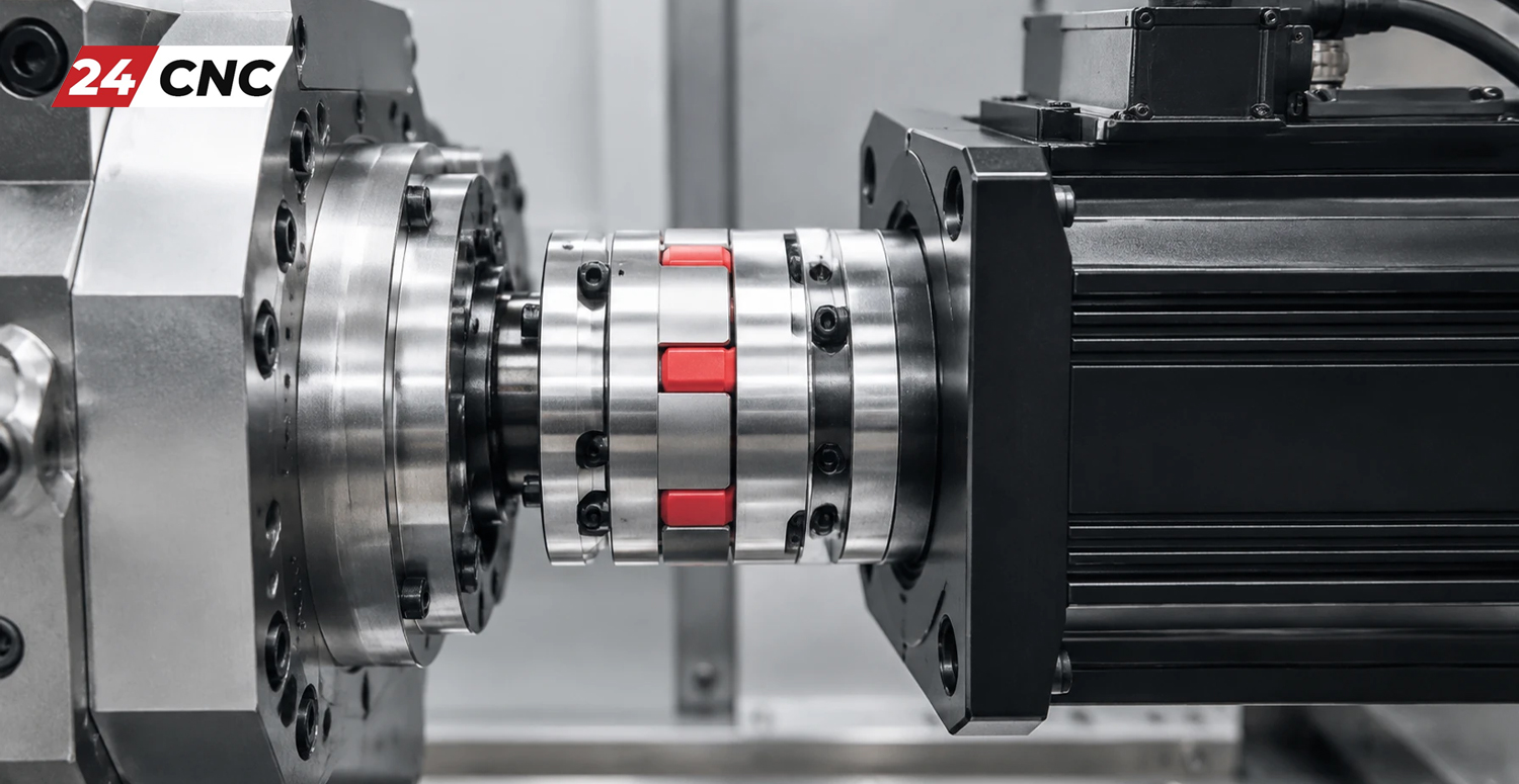
Even the highest quality coupling will fail or induce error if installed incorrectly. Follow these strict engineering guidelines during assembly:
- Clean the Shafts: Before sliding the coupling onto the motor or ball screw shaft, ensure both shafts are completely free of oil, grease, rust, or debris. A clamping style coupling relies 100% on friction; any lubricant on the shaft will drastically reduce its torque-holding capacity and lead to slippage. Wipe shafts with a fast-drying solvent like acetone.
- Observe Insertion Depth: Do not push the shaft so far into the coupling that it interferes with the flexible discs. The shaft should fully support the clamping hub but remain clear of the flexing elements. Most premium couplings have internal mechanical stops or visible insertion depth lines.
- Use a Torque Wrench: Never guess the tightening torque of the clamping bolts. Use a calibrated torque wrench and tighten the bolts exactly to the coupling manufacturer’s specifications. Under-tightening causes slip; over-tightening can deform the aluminum hub or strip the bolt threads.
- Verify Alignment After Installation: Use a dial indicator to sweep the coupling hubs while manually rotating the axis. Even flexible couplings have limits; minimizing the initial misalignment extends the fatigue life of the stainless steel discs exponentially.
Frequently Asked Questions (FAQ)
Why did the stainless steel discs in my coupling break or deform?<
Disc pack failure is almost exclusively caused by operating the coupling beyond its rated misalignment tolerances. If the parallel offset between the motor and ball screw is too large, the discs suffer severe metal fatigue with every rotation and eventually snap. Excessive peak torque (a machine crash) can also permanently deform the discs.
Can I use an elastomer jaw coupling instead of a disc coupling for a CNC axis?
It is highly discouraged for precision axes. Jaw couplings use a rubber/polyurethane insert. Under the rapid reversing loads of a CNC servo, this insert compresses, introducing a spongy, elastic delay. This destroys your machine’s ability to interpolate accurate circles and ruins the servo system’s high-frequency tuning, often resulting in axis vibration.
What happens if the coupling slips on the motor shaft?
If the coupling slips, the servo motor’s encoder (which tracks position) will lose its physical synchronization with the actual position of the machine table. The machine will cut parts out of tolerance without throwing an immediate error, although severe slippage will eventually trigger a following error or positional deviation alarm in the CNC controller.
Upgrade Your Machine’s Precision Today
Stop losing microns to inferior power transmission. Whether you are rebuilding a high-speed machining center or upgrading standard automation equipment, choosing the correct zero-backlash coupling is critical. Let the experts at 24CNC help you select the exact specifications for your motor.
Leave a comment
Your email address will not be published. Required fields are marked *