

When it comes to precision manufacturing, the heart of your CNC milling machine, lathe, or router is undeniably the spindle. Operating at staggering speeds—often ranging from 10,000 to well over 40,000 Revolutions Per Minute (RPM)—even the most microscopic imperfection in mass distribution can lead to catastrophic consequences. This comprehensive dynamic spindle balancing guide for CNC will take you through the critical physics of unbalance, the symptoms of a poorly balanced spindle, and the exact step-by-step methodology required to restore your machinery to optimal, vibration-free performance.
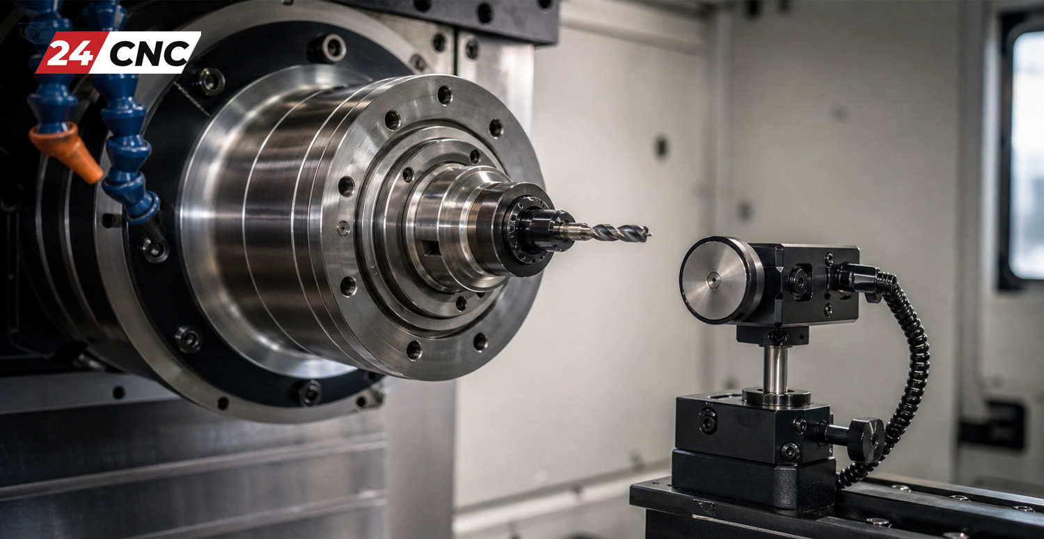
What is Dynamic Spindle Balancing and Why is it Critical?
In the realm of rotational mechanics, “unbalance” occurs when the center of mass of a rotating object does not perfectly align with its center of rotation (the geometric axis). As the spindle rotates, this offset mass generates a centrifugal force. Because centrifugal force increases exponentially with the square of the rotational speed ($F = mr\omega^2$), an unbalance that is entirely unnoticeable at 1,000 RPM can generate violent, destructive forces at 15,000 RPM.
Dynamic spindle balancing is the highly precise process of measuring this unbalance using vibration analyzers and applying corrective weights (or removing mass) at specific phase angles across two different rotational planes. This corrects the “wobble” (dynamic unbalance) and ensures the spindle rotates smoothly around its true geometric axis.
Incorporating spindle balancing into your CNC machine maintenance checklist is not a luxury; it is a fundamental requirement for any shop aiming for high precision, long tool life, and maximum machine uptime.
Symptoms of an Unbalanced CNC Spindle
Ignoring spindle unbalance is one of the most expensive mistakes a machine shop can make. The symptoms often start subtly but compound rapidly, affecting every aspect of the machining process.
- Premature Bearing Failure: High-precision angular contact bearings (often ceramic hybrid) are designed to handle immense axial and radial loads, but continuous micro-hammering from a vibrating spindle will destroy their raceways. Replacing spindle bearings is notoriously expensive and results in massive downtime.
- Degraded Surface Finish: If you are noticing “chatter marks,” wave patterns, or a faceted, uneven finish on your milled parts, vibration is the likely culprit. Dynamic unbalance translates directly to the cutting tool, causing it to bounce against the workpiece rather than slice cleanly.
- Shortened Tool Life: Solid carbide end mills are exceptionally hard but highly brittle. The micro-vibrations caused by an unbalanced spindle result in micro-chipping along the cutting edge of the tool, cutting its effective lifespan in half and increasing your consumable costs.
- Spindle Taper Fretting: Excessive vibration can cause microscopic movement between the toolholder and the spindle taper, leading to fretting wear. Once the taper is damaged, no toolholder will seat correctly, permanently ruining your machine’s accuracy until the taper is reground.
It is also important to differentiate mechanical unbalance from electrical issues. For instance, irregular torque ripples from the drive can sometimes mimic mechanical vibration. If you suspect an electrical drive fault is causing uneven rotation, you must understand the difference between drives. Refer to our guide on spindle drive vs servo drive, and you may need to test or replace CNC spindle IGBT modules before proceeding with mechanical balancing.
Understanding ISO 1940-1 Balancing Grades (G2.5 vs G1.0)
When professionals talk about dynamic balancing, they refer to the ISO 1940-1 standard. This international standard defines the acceptable limits of residual unbalance based on the mass of the rotor and its maximum operating speed. The “G” stands for the balancing grade.
- Grade G6.3: Generally acceptable for standard machinery parts like fans, pump impellers, and normal electric motor armatures. It is not acceptable for high-speed CNC spindles.
- Grade G2.5: The industry standard for modern CNC machine tool spindles, gas turbines, and computer memory drums. If you are milling at 10,000 to 15,000 RPM, achieving a G2.5 balance is absolutely mandatory for smooth operation.
- Grade G1.0: The ultra-precision standard. This is required for high-speed grinding spindles, micromachining spindles operating at 30,000 to 60,000+ RPM, and audio/video drives. Achieving G1.0 requires an incredibly clean environment, flawless bearings, and meticulously balanced tooling.
The calculation for allowable residual unbalance takes into account the target RPM. A spindle balanced to G2.5 at 10,000 RPM will require a much tighter mechanical tolerance than a massive lathe chuck balanced to G2.5 at only 1,500 RPM.

Step-by-Step Dynamic Spindle Balancing Process
Dynamic balancing can be performed in-situ (while the spindle is mounted inside the CNC machine) or on a dedicated balancing bench during a full spindle rebuild. In-situ balancing is highly preferred for routine maintenance as it accounts for the entire system’s mass, including the drawbar, bearings, and motor rotor. Here is the professional procedure:
Step 1: Preparation and Cleaning
Before attaching any sensitive CNC sensors, thoroughly clean the spindle nose and taper. Even a small chip of aluminum or a drop of dried coolant inside the taper can throw off the balance reading. Ensure the machine is warmed up; run the spindle at 50% max RPM for 15 minutes to allow the bearings to reach their normal operating temperature and properly distribute lubrication.
Step 2: Sensor Placement (Accelerometers and Tachometer)
Attach a vibration sensor (typically a high-frequency piezoelectric accelerometer) as close to the front spindle bearing as possible. A solid, magnetic mount on a flat, clean surface of the spindle housing is required. Next, apply a piece of reflective tape to the rotating face of the spindle and mount a laser tachometer (photoelectric sensor) to point directly at it. The tachometer provides the exact RPM and serves as the 0-degree reference phase angle, allowing the analyzer software to know exactly where the heavy spot is located in the 360-degree rotation.
Step 3: Taking the Baseline Reading
Run the spindle up to the target balancing speed. This speed should closely reflect the RPM where you experience the most vibration, or the maximum operating speed of the machine. The analyzer will display the overall vibration amplitude (usually in mm/s or inches/sec velocity) and the phase angle of the unbalance. This is your baseline. If the baseline is already below the target ISO tolerance, no further action is needed.
Step 4: The Trial Mass Run
Stop the spindle completely. Add a “trial weight” of a known mass (e.g., a 1-gram set screw or piece of specialized balancing putty) at a known angle on the spindle’s balancing ring. Run the spindle back up to the exact same speed. The analyzer will measure how the vibration amplitude and phase angle have changed. By comparing the baseline run with the trial mass run, the software calculates the exact “influence coefficient” of the spindle system.
Step 5: Applying the Correction Mass
Based on the vector math calculated in Step 4, the analyzer will output a specific correction. It will tell you exactly how much weight to add (or drill away) and at what precise angle. Most high-end CNC spindles feature a threaded balancing ring with M4 or M5 holes specifically designed for adding small grub screws as counterweights. Apply the exact weight recommended at the exact location.
Step 6: Final Verification (Trim Run)
Remove the trial weight and ensure only the correction weights are installed. Run the spindle one final time. If the correction was precise, the vibration amplitude should drop drastically, falling well below the threshold for ISO G2.5 or G1.0. If slight vibration remains, the analyzer will suggest a secondary “trim” correction. Repeat the trim runs until the spindle runs perfectly smooth.
The Role of Toolholders in Spindle Balancing
It is absolutely critical to remember that the spindle does not cut metal by itself; the toolholder, pull stud, and the cutting tool become part of the rotating mass. You can spend thousands of dollars balancing your spindle perfectly to G1.0, but if you insert a cheap, unbalanced ER collet chuck into the taper, you have entirely ruined the dynamic balance of the system.
For machines operating over 10,000 RPM, you must use dynamically balanced toolholders (such as shrink-fit, hydraulic, or high-precision mechanical collet chucks that come factory-balanced). Furthermore, whenever taking baseline measurements for spindle balancing, ensure the spindle is empty, or use a certified, pre-balanced “master test arbor.” Balancing a spindle with a random toolholder inserted means you are simply balancing the spindle to that specific toolholder. The moment the automatic tool changer (ATC) swaps to a different tool, severe vibration will return.

Technical Comparison: In-Situ vs. Bench Balancing
There are two primary environments where dynamic balancing takes place. Understanding which method to use depends entirely on the state of your machinery.
| Feature / Aspect | In-Situ Balancing (In-Machine) | Bench Balancing (Shop Rebuild) |
|---|---|---|
| Primary Use Case | Routine maintenance, post-crash tuning, reducing minor vibrations on healthy bearings. | Complete spindle rebuilds, bearing replacements, manufacturing of new spindle shafts. |
| System Integration | Balances the entire rotating assembly (drawbar, motor rotor, belts) together as a true unit. | Balances only the bare spindle shaft. System dynamics may change slightly upon final machine installation. |
| Correction Method | Non-destructive (Adding grub screws to threaded balance rings). | Destructive or Non-destructive (Drilling material away, grinding, or adding permanent weights). |
| Downtime | Very Low (Usually 2 to 4 hours directly on the shop floor). | Very High (Requires complete spindle removal, shipping to a specialist, and re-installation). |
| Cost | Highly cost-effective. Prevents future bearing damage. | Expensive (Always associated with a full teardown and precision bearing replacement). |
Common Spindle Vibration Causes Unrelated to Balance
Before committing to a dynamic balancing procedure, you must rule out other mechanical and electrical issues that masquerade as unbalance. If you attempt to balance a spindle suffering from the following defects, you will chase phantom vibrations endlessly:
- Failing Bearings: If the ceramic balls are pitted or the cages are failing, the spindle will vibrate erratically. Balancing cannot fix bad bearings. A vibration analyzer can detect bearing fault frequencies (BPFO, BPFI) to confirm this before you attempt to balance.
- Bent Drawbar: A hard crash can bend the internal drawbar. Because the drawbar rotates with the spindle, a bent shaft will throw the mass drastically out of center.
- Belt Resonance: On belt-driven spindles, a worn, misaligned, or improperly tensioned drive belt can introduce harsh vibrations at specific RPMs (resonance frequencies) that vanish at other speeds.
- Loose Machine Mounting: If the spindle cartridge is not torqued down correctly, or the machine leveling pads are loose, the entire casting can resonate.
Frequently Asked Questions (FAQ)
How often should I dynamically balance my CNC spindle?
It highly depends on machine usage and operating speeds. For continuous high-speed machining (above 15,000 RPM), a preventative vibration analysis and potential trim balance should be performed annually. However, you should immediately check the dynamic balance after any significant tool crash, as the impact can shift internal components.
Can I balance a spindle if the bearings are already making noise?
No. If the bearings are spalled, pitted, or lacking preload, the spindle shaft will shift dynamically under load. The vibration analyzer will give you erratic, unrepeatable phase angles, making mathematical balancing impossible. You must replace faulty bearings before attempting to balance the rotor.
Is it better to add weight or remove weight during correction?
Adding weight (via calibrated set screws in pre-drilled threaded balancing rings) is the preferred, non-destructive method for in-situ balancing on the shop floor. Removing weight (drilling or grinding) is typically done during the original manufacturing stage or during bench rebuilds. Drilling inside the machine risks introducing metal chips into sensitive labyrinth seals.
What is the difference between single-plane and two-plane balancing?
Single-plane balancing corrects static unbalance and is usually sufficient for very narrow rotors like a thin flywheel or a grinding wheel. Two-plane balancing measures and corrects vibration at both ends of a long cylinder independently, resolving dynamic “wobble” (couple unbalance). Because CNC spindles are long cylinders, they almost always require strict two-plane dynamic balancing.
Conclusion: Protecting Your CNC Investment
Mastering dynamic spindle balancing is not just about reducing acoustic noise; it is about protecting the expensive heart of your CNC machine tool. A perfectly balanced spindle runs significantly cooler, extends the life of costly ceramic bearings, dramatically increases solid carbide tool longevity, and yields mirror-like surface finishes on your precision workpieces. Whether you rely on outside technicians for routine vibration analysis or invest in your own dynamic balancing hardware, ensuring strict adherence to ISO G2.5 or G1.0 standards is the hallmark of a world-class manufacturing facility.
By understanding the physics of centrifugal force, recognizing the early warning signs of chatter and excessive heat, and following a rigid step-by-step methodology, you can prevent catastrophic failures before they shut down your production lines. Always remember that the spindle is only as balanced as the toolholder you put into it.
Keep Your Machine Running at Peak Performance
Don’t wait for a costly spindle failure to halt your production schedule. Whether you are hunting down phantom vibrations, upgrading your sensors, or repairing your spindle drives, 24CNC provides industry-leading, high-quality components to keep your machinery balanced and deadly accurate.
Leave a comment
Your email address will not be published. Required fields are marked *