

The beating heart of any CNC machine’s mechanical longevity is its central lubrication system. Without a steady, precisely measured flow of way lube, metal grinds against metal. Within a matter of days—sometimes hours—lack of lubrication can destroy expensive precision ball screws and severely score linear guideways. Understanding CNC central lubrication pump troubleshooting is not just a maintenance skill; it is a critical requirement for any machine operator or maintenance technician who wants to prevent catastrophic machine failure and costly downtime.
A central lubrication pump is responsible for drawing oil (or fluid grease) from a reservoir and pushing it through a complex network of hoses, manifolds, and metering valves (restrictors) to every moving axis of the machine. When a low-pressure alarm halts your CNC program mid-cycle, or when you notice the bedways looking dangerously dry, you need to know exactly how to diagnose the root cause. In this comprehensive guide, we will break down the anatomy of the lube system, the most common failure points, and the step-by-step procedures to bring your lubrication system back to optimal health.
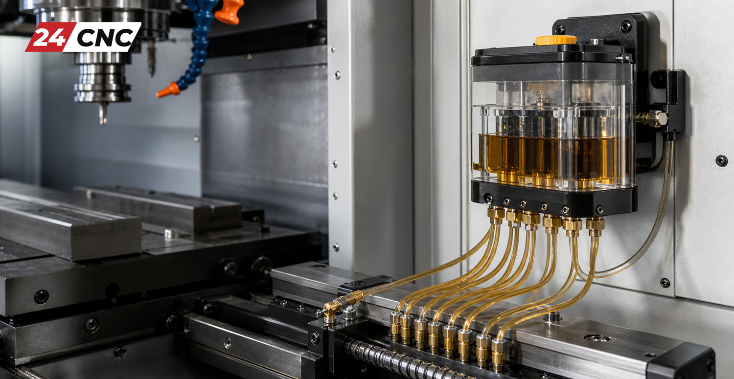
How a CNC Central Lubrication System Works
Before diving into troubleshooting, it is essential to understand the basic mechanics of an automatic lubrication system. Most modern CNC mills and lathes use a timer-based or pulse-based volumetric lubrication system. This system consists of several key components:
- The Reservoir: The tank that holds the lubricating oil (commonly way oils like Mobil Vactra No. 2). It usually features a low-level float switch to trigger an alarm before it runs dry.
- The Pump Unit: Typically a motorized gear pump or a pneumatic piston pump that pressurizes the system.
- The Pressure Switch: A crucial sensor that verifies the system has reached the required operating pressure. If the pressure isn’t met within a specific timeframe, the CNC controller generates a lube alarm.
- Manifolds and Lines: The plumbing that distributes the oil throughout the machine. Nylon tubing or flexible steel-braided lines are common.
- Metering Valves (Restrictors): Located at the end of the lines near the moving parts. These valves meter out an exact volume of oil (e.g., 0.1cc, 0.3cc) to the linear guides and ball screw nuts every time the system pressurizes.
Common Symptoms of CNC Lube Pump Failure
Troubleshooting starts with observation. Recognizing the early warning signs of lubrication failure can save your machine from permanent mechanical damage. Keep an eye (and ear) out for these common symptoms:
- Persistent “Low Lube Pressure” Alarms: The most common indicator. The machine’s PLC triggers this when the pressure switch does not detect the target pressure within the allotted pump run time.
- Dry Way Surfaces: If you wipe your finger across the linear rails or box ways and they are completely dry or covered in sticky, dried-up residue, oil is not reaching the destination.
- Excessive Oil Consumption: If you find yourself filling the lube tank far more frequently than usual, or if the coolant sump is suddenly overflowing with tramp oil, you likely have a blown line or a broken fitting.
- Unusual Noises: A grinding, whining, or clicking noise coming from the pump motor itself indicates internal mechanical wear or a stripped gear inside the pump housing.
- Sticky or Jerky Axis Movement: Also known as “stick-slip.” Without oil, the friction between the ways and the saddle increases drastically, causing the axis servos to work harder, sometimes resulting in tracking errors or poor surface finishes on machined parts.
Step-by-Step Troubleshooting Guide
When faced with a lubrication issue, follow this systematic approach to isolate and resolve the problem efficiently.
1. Inspecting the Reservoir and Fluid Quality
Start with the absolute basics. Is there oil in the tank? Sometimes, the float switch inside the reservoir gets stuck in the “full” position due to sludge buildup, tricking the control system into thinking there is plenty of oil when the tank is actually empty. Clean the tank thoroughly. Ensure you are using the correct viscosity of oil. Using standard hydraulic oil instead of specialized way lube (which contains tackifiers to help it cling to vertical surfaces) will cause the oil to run off too quickly, leaving the ways unprotected.
2. Diagnosing Low-Pressure Alarms (The “Bleed Down” Test)
If the pump runs but the system fails to reach pressure, you either have a weak pump, a faulty pressure switch, or a massive leak. To isolate a leak:
Most central lubrication systems have a main output line leaving the pump. Disconnect this line and cap the pump’s output port with a threaded plug. Manually trigger the pump. If the pump instantly builds pressure and holds it (and the pressure switch registers it, clearing the alarm), your pump is perfectly fine. The problem lies downstream—you have a broken line or a blown fitting somewhere inside the machine’s casting.
If, however, the capped pump still cannot build pressure, the internal gears of the pump are worn out, the internal relief valve is stuck open, or the intake filter screen at the bottom of the tank is heavily clogged with debris.
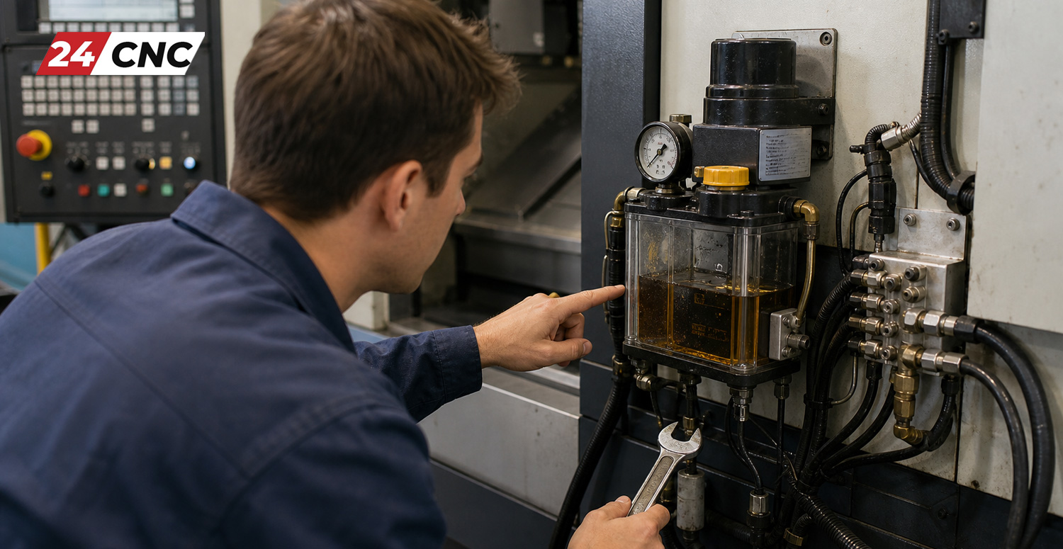
3. Hunting Down Broken Lines and Manifold Leaks
If your “cap test” proved the pump is healthy, you must find the leak. This is often the most time-consuming part of CNC central lubrication pump troubleshooting. You will need to remove way covers to visually inspect the flexible lines connecting to the moving axes (X, Y, and Z). Because these lines constantly flex as the machine moves, they become brittle over time and snap. A single broken line will cause the entire system to lose pressure, starving every other component of oil. Replace broken lines using high-quality nylon tubing or braided steel hoses, ensuring they have adequate slack for full axis travel.
4. Dealing with Clogged Metering Valves (Restrictors)
If your system reaches pressure successfully but a specific axis remains dry, the metering valves for that axis are clogged. Over years of operation, impurities in the oil, microscopic brass particles, or mixed incompatible oils can form a thick waxy sludge that completely blocks the tiny orifices inside the restrictors.
Crucial Rule: Never try to clear a clogged restrictor by blowing compressed air through it or soaking it in solvent. Metering valves contain precise spring-loaded check valves and tiny filtration screens. Once they clog, they are permanently compromised. You must replace them. When replacing restrictors, always replace them with the exact same volumetric rating (e.g., swapping a size 3 for a size 3). Changing the size alters the hydraulic balance of the entire manifold block.
5. Electrical and Timer Issues
Sometimes the mechanical plumbing is perfect, but the pump never turns on. This points to an electrical issue. Check the power supply to the pump motor. Many automated pumps run on 110V AC or 24V DC. Use a multimeter to verify voltage is reaching the pump when the CNC controller commands a lubrication cycle. If there is no voltage, trace the wiring back to the electrical cabinet. Check for blown fuses, tripped thermal overloads, or a failed relay on the I/O board. Additionally, ensure the lubrication timer parameters in your CNC controller (which dictate how long the pump runs and how long it pauses between cycles) haven’t been accidentally altered or corrupted.
Technical Comparison: Automatic vs. Manual Lubrication Systems
Understanding the differences between system types helps in accurate diagnostics and setting up your maintenance checklist.
| Feature | Automatic Volumetric System | Manual/One-Shot System |
|---|---|---|
| Actuation Method | Controlled automatically by the CNC PLC timer. | Requires operator to pull a manual lever. |
| Pressure Monitoring | Includes a pressure switch to trigger controller alarms. | No electronic feedback; relies on operator feel. |
| Typical Application | Production CNC Mills, Lathes, and heavy industrial machinery. | Manual milling machines (Bridgeport style), toolroom lathes. |
| Maintenance Priority | High. Requires routine line inspections and restrictor replacement. | Low. Mostly requires keeping the reservoir filled. |

Preventative Maintenance Best Practices
The best way to handle CNC central lubrication pump troubleshooting is to prevent the issues from occurring in the first place. Adopting a strict preventative maintenance routine will extend the life of your entire machine.
- Use the Right Oil: Never mix different brands or types of way lube. Chemical reactions between additives can create sludge that instantly clogs metering valves. Always use the manufacturer’s recommended fluid.
- Keep the Tank Clean: Dust, coolant mist, and shop debris can find their way into the lube tank. At least once a year, drain the tank completely, wipe out the bottom to remove sediment, clean the suction filter screen, and refill with fresh oil.
- Inspect Way Covers: Damaged way covers allow metal chips to drag across the linear guides, scraping away the protective oil film and physically damaging the lubrication lines hidden beneath.
- Monitor Cycle Times: If you notice the pump takes significantly longer to reach operating pressure than it used to, the pump gears are wearing out. Order a replacement pump before it fails completely and stops production.
Frequently Asked Questions (FAQ)
Why does my CNC machine throw a lube alarm right after I turn it on?
When the machine boots up, the PLC immediately runs a lube cycle to pre-lubricate the ways. If the pressure switch doesn’t detect a rise in pressure within 10 to 15 seconds (due to a broken line, an empty tank, or a faulty pump), the machine throws a safety alarm to prevent the axes from moving dry.
Can I clean and reuse clogged metering restrictor valves?
No. Metering valves are delicate, precisely calibrated devices containing tiny springs and check valves. Solvents or compressed air will damage the internal mechanism. They are consumable items and must be replaced when clogged.
How often should my automatic lubrication pump cycle?<
This depends heavily on the machine’s size and the manufacturer’s design. Typically, a CNC mill will cycle the lube pump for 10-15 seconds every 15 to 30 minutes of actual axis movement. You can usually view and adjust these timer parameters in your machine’s control system, though you should rarely deviate from factory settings.
What happens if the pressure relief valve is stuck open?
If the pump’s internal pressure relief valve is stuck open (often caused by a piece of debris), the oil will simply bypass the outlet and circulate back into the tank. The pump motor will run, but zero pressure will be delivered to the machine’s lines, resulting in a persistent low-pressure alarm.
Need High-Quality Replacement Parts for Your CNC Machine?
Don’t let a failed lubrication pump or a broken line halt your production. Ensure your machine runs smoothly and accurately with premium replacement components.
Leave a comment
Your email address will not be published. Required fields are marked *