
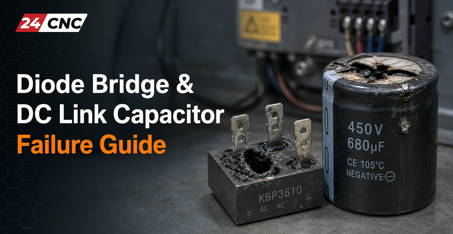
In the complex and demanding world of CNC machining, the reliability of your electrical components dictates the uptime and profitability of your entire operation. At the heart of every CNC machine’s motion control system—powering the high-speed spindles and precise servo motors—lies the power conversion section of the drive. The unsung heroes of this section are the diode bridge (rectifier) and the DC link capacitors. When these components fail, production grinds to a halt. This comprehensive diode bridge & DC link capacitor failure guide is engineered to help maintenance professionals, CNC technicians, and workshop owners identify, diagnose, and resolve fatal power stage issues before they cascade into catastrophic drive failures.
Whether you are dealing with a sudden drive explosion, mysterious undervoltage alarms, or erratic spindle behavior, understanding the symbiotic relationship between your rectifier and DC bus is critical. Let’s dive deep into how these components operate, why they fail, and how you can definitively test them using standard diagnostic tools.
Introduction to CNC Power Sections: The Rectifier and DC Bus
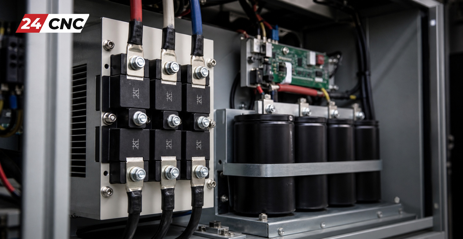
Before jumping into failure analysis, it is essential to understand the architecture of standard amplifier and inverter systems used in CNC machines. Most variable frequency drives (VFDs) and servo amplifiers utilize a three-stage power conversion process:
- The Converter (Diode Bridge Rectifier): This front-end stage takes incoming 3-phase AC voltage from your facility’s power grid and converts it into raw, pulsating DC voltage.
- The DC Link (Capacitor Bank): This intermediate stage acts as an energy reservoir and a massive filter. The DC link capacitors smooth out the ripples from the raw DC voltage, providing a stable, clean, and continuous DC bus voltage.
- The Inverter (IGBT Section): The final stage takes the clean DC voltage and rapidly switches it on and off using IGBT modules to create a simulated AC waveform of varying frequency and voltage, which precisely controls the motor.
Because the diode bridge and the DC link capacitors sit right next to each other in this circuit (electrically speaking), a failure in one almost always puts immense stress on the other. Diagnosing and troubleshooting CNC servo amplifier alarms correctly requires looking at both components simultaneously.
Understanding the Diode Bridge (Rectifier)
How a Diode Bridge Works in Servo Drives
A 3-phase diode bridge rectifier typically consists of six high-power diodes arranged in a specific bridge configuration. Diodes act as one-way electrical valves, allowing current to flow in only one direction. As the three phases of AC power cycle through their positive and negative peaks, the diodes direct all the positive halves to the positive DC bus terminal and all the negative halves to the negative DC bus terminal. The result is a continuous, though rippled, flow of DC power.
Symptoms of a Failing Diode Bridge
When a diode bridge fails, it generally does so in one of two ways: a short circuit or an open circuit. The symptoms can range from subtle performance issues to immediate catastrophic failure.
- Blown Main Input Fuses: A shorted diode will allow AC phases to cross or short directly to the DC bus, causing a massive current draw that instantly blows the incoming supply fuses or trips the main workshop breaker.
- Drive Will Not Power On: If multiple diodes fail open, the DC bus will never charge up. The drive’s internal low-voltage power supply (which usually runs off the DC bus) will not start, leaving the control screen completely dead.
- Phase Loss Alarms: If only one diode out of the six fails open, the drive will still generate DC power, but it will suffer from excessive voltage ripple. Many modern CNC controllers will detect this imbalance and throw an input phase loss alarm.
- Excessive Heat Generation: A degraded diode bridge that hasn’t fully failed will have a higher internal resistance, turning electrical energy into excessive heat and causing the drive’s heat sink temperatures to spike.
How to Test a Diode Bridge
You can easily test the integrity of a diode bridge using a standard digital multimeter set to the “Diode Test” function. Safety Warning: Always ensure all power is disconnected and the DC bus is completely discharged (measuring 0V DC) before testing.
- Test the Upper Diodes: Place the positive (red) probe on the negative (-) DC bus terminal. Touch the negative (black) probe to each of the three incoming AC phase terminals (L1, L2, L3) one by one. You should read a forward voltage drop of approximately 0.3V to 0.7V on each leg. Reverse the probes; you should read “OL” (Open Loop) indicating the diode is blocking reverse flow.
- Test the Lower Diodes: Place the negative (black) probe on the positive (+) DC bus terminal. Touch the positive (red) probe to the AC phase terminals (L1, L2, L3). Again, you should see 0.3V to 0.7V. Reversing the probes should show “OL”.
If any reading shows a dead short (0.00V) or remains open (“OL”) in both directions, the diode bridge module is destroyed and must be replaced. This testing method is structurally similar to what you would use when testing and replacing CNC spindle IGBT modules.
Demystifying the DC Link Capacitor
The Role of DC Link Capacitors
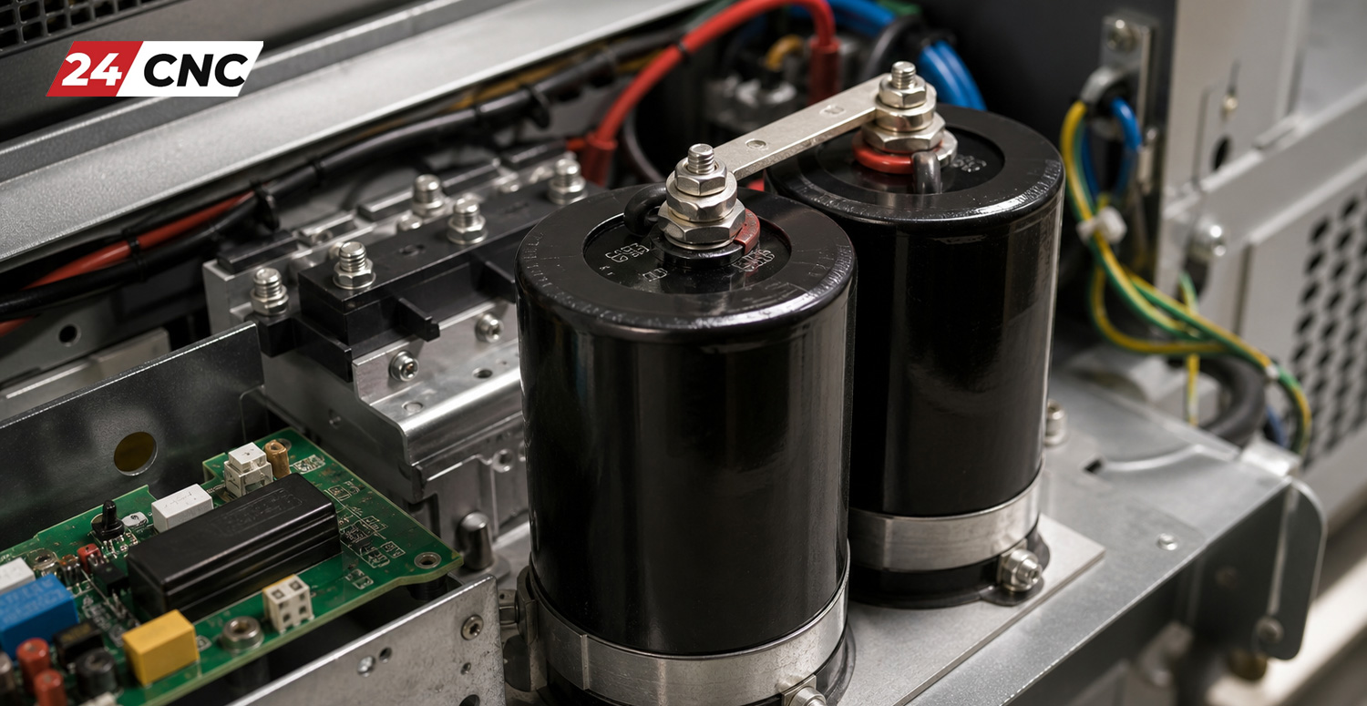
If the diode bridge is the heart pumping raw voltage, the DC link capacitors are the lungs, smoothing and stabilizing the flow. Large electrolytic capacitors are placed across the positive and negative DC bus rails. They charge up during the voltage peaks provided by the rectifier and discharge slightly during the valleys, resulting in a smooth, flat DC voltage line. They also provide instantaneous peak current to the inverter section when the servo motor demands sudden, rapid acceleration.
Signs of DC Link Capacitor Degradation and Failure
Unlike diode bridges which often fail instantaneously, aluminum electrolytic capacitors suffer from wear and tear. Over time, the internal wet electrolyte slowly dries out, particularly in hot environments. As they degrade, their Equivalent Series Resistance (ESR) increases, and their overall capacitance decreases.
- Undervoltage Alarms: Because degraded capacitors cannot hold enough charge, the DC bus voltage will momentarily collapse when the motor draws heavy current. This is the leading cause of drive errors, and you should always check the capacitors when trying to fix a main circuit undervoltage A410 alarm.
- Visual Bulging or Venting: The most obvious sign of capacitor failure is visual. Inspect the top of the cylindrical capacitors. If the metal top is bulging outward, or if you see dried, crusty brown electrolyte leaking from the safety vent, the capacitor has failed.
- Overvoltage Faults During Deceleration: Capacitors absorb the regenerative energy pushed back by the motor during braking. If they have lost their capacity, the bus voltage will spike too high, too fast. While this can also relate to braking resistors, bad caps make fixing A400 overvoltage errors impossible until they are replaced.
- Audible Whining or Popping: In extreme cases, failing capacitors will emit a high-pitched whine or physically pop audibly when the internal pressure bursts the safety seal.
Testing and Replacing DC Bus Capacitors
While visual inspection catches many bad capacitors, definitive testing requires specialized tools. A standard multimeter can measure total capacitance, but it cannot measure ESR. A dedicated LCR meter or ESR meter is required. If the measured capacitance has dropped by more than 20% of its rated value, or if the ESR has increased significantly above the manufacturer’s spec sheet, the entire bank must be replaced.
Crucial Rule: Never replace just one capacitor in a series/parallel DC link bank. Always replace all of them at the same time with exact matching replacements. Mixing old and new capacitors causes uneven voltage distribution, leading to the rapid destruction of the new capacitors.
Common Causes of Combined Bridge and Capacitor Failures
These two components are inextricably linked. A failure in one often causes the death of the other. Understanding IGBT modules in CNC drives and power stages reveals how electrical stress propagates.
- The Vicious Cycle of High Ripple: If the DC link capacitors degrade, they fail to smooth the DC voltage. This massive voltage ripple forces the diode bridge to work exponentially harder, dealing with high peak currents rather than a steady flow. Over time, the diode bridge will overheat and short out. Conversely, if a diode fails open, the capacitors are forced to handle an asymmetric load, causing massive internal heating and rapid electrolyte boil-off.
- Voltage Spikes and Lightning Surges: A massive external power surge will blow right past the protective MOVs (Metal Oxide Varistors), instantly shorting the diode bridge and potentially rupturing the DC link capacitors due to sheer overvoltage.
- Aging and Thermal Stress (The Bathtub Curve): Both components are highly susceptible to heat. If the cooling fans on your CNC drive fail or if the heat sink is clogged with machining coolant and dust, the internal temperature skyrockets. For every 10°C rise in operating temperature, the lifespan of an electrolytic capacitor is cut in half.
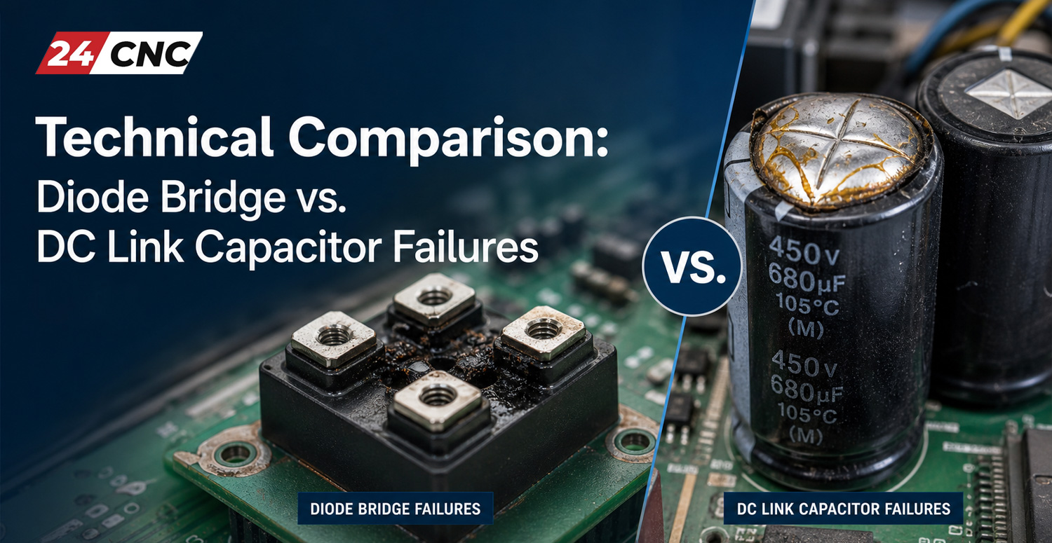
Technical Comparison: Diode Bridge vs. DC Link Capacitor Failures
| Component | Primary Symptoms | Root Causes | Diagnostic Method |
|---|---|---|---|
| Diode Bridge (Rectifier) | Blown input fuses, tripped breakers, dead control screen, phase loss alarms. | Power surges, excessive capacitor ripple, thermal overload, manufacturing defect. | Multimeter in “Diode Test” mode. Check for 0.3V-0.7V forward, OL reverse. |
| DC Link Capacitor Bank | Undervoltage faults under load, overvoltage faults braking, physical bulging/leaking. | Age/electrolyte dry-out, high ambient temperatures, single-phasing of input power. | Visual inspection for venting. Measure Capacitance and ESR with LCR meter. |
Preventative Maintenance for CNC Drives
Preventing the failure of your diode bridge and DC link capacitors is far cheaper than replacing a blown drive and dealing with machine downtime. Implementing a robust maintenance schedule is non-negotiable.
- Thermal Imaging: Perform routine thermal imaging scans on your electrical cabinets while the machine is running under heavy load. Hotspots on the rectifier bridge or uneven temperatures across the capacitor bank are early warning signs of impending failure.
- Cabinet Climate Control: Ensure your CNC electrical cabinet’s AC unit or heat exchanger is functioning perfectly. Keeping ambient temperatures below 40°C (104°F) is crucial for capacitor longevity.
- Capacitor Reforming: If you keep spare drives on the shelf for emergencies, be aware that electrolytic capacitors degrade when not energized. Spare drives should be powered up (reformed) slowly using a variable transformer (Variac) for a few hours at least once a year to rebuild the capacitor’s internal oxide layer.
- Power Quality Audits: Periodically check the incoming 3-phase power to your shop. Voltage unbalance greater than 3% will severely strain the diode bridge and increase DC ripple.
Frequently Asked Questions (FAQ)
How often should DC link capacitors be replaced?
Under normal operating conditions and optimal cooling, most high-quality electrolytic capacitors have a lifespan of 5 to 7 years (approximately 40,000 to 60,000 operational hours). In hot environments or under heavy, continuous cyclical loading, preventative replacement is recommended every 4 to 5 years.
Can a blown diode bridge damage my IGBT modules?
Yes, absolutely. While the DC link capacitors usually act as a buffer, a violent short circuit in the diode bridge can cause massive voltage transients that punch through the protective layers of the IGBT modules downstream. Always test the IGBTs if the diode bridge has failed catastrophically.
Why is my drive showing an undervoltage alarm only when the spindle accelerates?
This is a classic symptom of dried-out DC link capacitors. The capacitors lack the stored energy required to supply the sudden burst of current the motor needs for acceleration. The voltage on the DC bus sags deeply, triggering the undervoltage alarm.
Can I measure DC bus voltage safely while the drive is running?
Yes, but extreme caution is required. The DC bus in a 400V AC system runs at nearly 600V to 700V DC—a lethal voltage. Only qualified personnel wearing appropriate PPE and using CAT III / CAT IV rated multimeters should attempt live voltage checks on the DC + and DC – terminals.
What is ESR, and why does it matter?
ESR stands for Equivalent Series Resistance. It is the internal resistance of the capacitor. As capacitors age, ESR rises. High ESR prevents the capacitor from absorbing and releasing energy quickly, and it causes the capacitor to generate excessive internal heat, accelerating its own death.
Experiencing CNC Drive Failures? We Have The Parts You Need!
Don’t let a blown diode bridge or failing DC link capacitors keep your machines down. Whether you need replacement power modules, new servo amplifiers, or precision diagnostic tools, 24CNC is your trusted partner for high-quality industrial components.
Leave a comment
Your email address will not be published. Required fields are marked *