
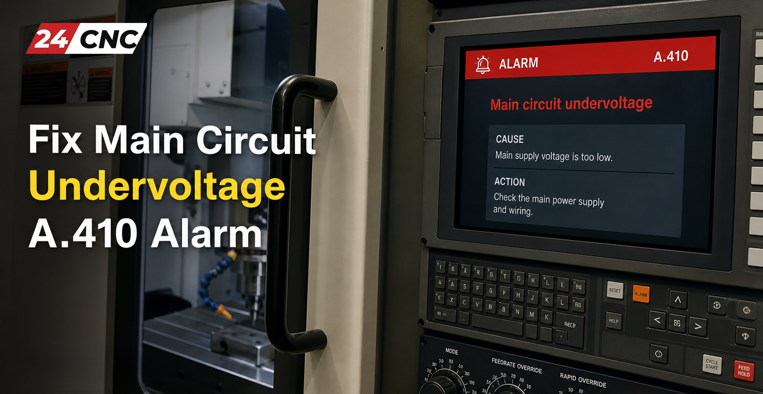
When operating a CNC machine or industrial automation system, unexpected downtime is your worst enemy. One of the most common and disruptive errors operators and maintenance engineers encounter is the Main Circuit Undervoltage A.410 Alarm. Predominantly seen in highly sophisticated servo drives like those manufactured by Yaskawa, this fault signifies a critical drop in the power being supplied to the main circuit of the amplifier. If ignored or improperly diagnosed, this issue can halt production, cause erratic motor behavior, or even result in severe hardware damage.
Understanding how to properly diagnose and troubleshoot CNC servo amplifier alarms is a non-negotiable skill for modern technicians. The A.410 alarm specifically acts as a safety mechanism, shutting down the drive to protect internal electronics when the DC bus voltage falls below acceptable operational thresholds.
In this comprehensive, step-by-step pillar page, we will explore exactly what the Main Circuit Undervoltage A.410 alarm is, the primary mechanical and electrical culprits behind it, and a methodical troubleshooting procedure to get your CNC machinery back online safely and efficiently.
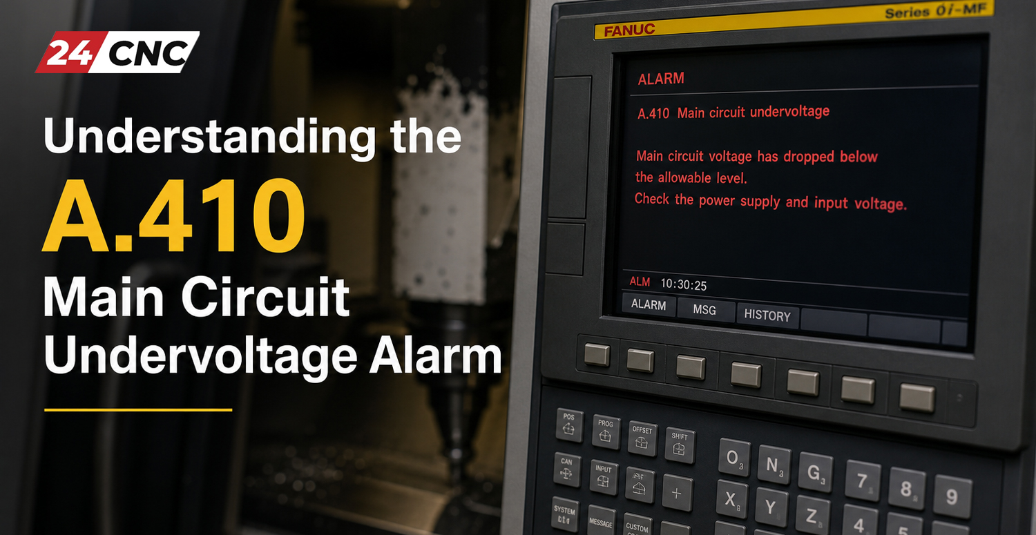
Understanding the A.410 Main Circuit Undervoltage Alarm
To successfully fix an A.410 alarm, you must first understand the architecture of a standard servo drive. Alternating Current (AC) power enters the drive from your facility’s power grid. This AC power passes through a rectifier circuit, converting it into Direct Current (DC). This internal DC power reservoir is known as the “DC Bus.” The inverter section of the drive then utilizes this DC bus voltage to create precise AC waveforms to command the servo motor.
What Does “Main Circuit Undervoltage” Actually Mean?
The A.410 alarm is triggered when the internal sensors of the servo amplifier detect that the DC bus voltage has dropped below the manufacturer’s safe threshold. For example, in a 200V-class servo drive, an undervoltage alarm might trigger if the DC bus drops below 150V DC. In a 400V-class drive, the threshold might be around 300V DC. Once this drop is detected, the drive’s internal microcontroller immediately ceases output to the motor and displays the A.410 code on the LED readout or the machine’s central control interface.
Common Symptoms on CNC Machines
When the A.410 alarm strikes, you will likely observe the following symptoms on your machine tool:
- Immediate Axis Stoppage: The machine will abort the current G-code cycle and apply holding brakes if equipped.
- Drive Fault LED: A blinking red LED or direct “A.410” readout on the front face of the servo amplifier.
- Control Panel Error: The main CNC controller will throw a generic “Servo Drive Not Ready” or specific “Z-Axis Drive Fault” warning.
- Relay Clicking: You may hear the main magnetic contactor unlatching (clicking off) inside the electrical cabinet.
Primary Causes of the A.410 Alarm
Diagnosing an undervoltage alarm requires a process of elimination. The root cause can be external to the machine (your building’s power grid), intermediate (wiring and contactors), or internal (the drive’s circuitry). Below are the four primary causes.
1. Input Power Supply Issues
The most frequent cause of an A.410 alarm is a problem with the incoming three-phase or single-phase power supply. Industrial environments often suffer from voltage sags, brownouts, or momentary power dips when heavy machinery (like massive compressors or stamping presses) is turned on. Additionally, a phenomenon known as “phase loss” (where one of the three AC phases drops out completely) will severely reduce the DC bus voltage, immediately triggering the A.410 alarm.
2. Faulty Wiring and Loose Connections
CNC machines vibrate intensely. Over thousands of hours of operation, screw terminals can loosen. A loose connection on the L1, L2, or L3 input terminals creates high electrical resistance. This resistance results in a localized voltage drop right before the power enters the drive. If the power cables are frayed, degraded, or loosely seated, the amplifier will starve for power.
3. Defective Magnetic Contactor or Relay
Before power reaches the servo amplifier, it usually passes through a magnetic contactor or a safety relay. Over time, the internal copper contacts within these devices suffer from arcing and pitting. When pitted, the contacts fail to provide a clean, low-resistance path for the electricity. A degraded contactor might show 220V on its input side but only deliver 180V to its output side under load.
4. Internal Servo Drive Failure
If external power is perfect, the fault lies within the CNC servo amplifiers and drives. The rectifier bridge (which converts AC to DC) or the large electrolytic capacitors (which smooth and store the DC voltage) may have degraded or failed. Furthermore, a failure in the internal voltage sensing circuit can cause the drive’s logic board to incorrectly “think” the voltage is low when it is actually fine.
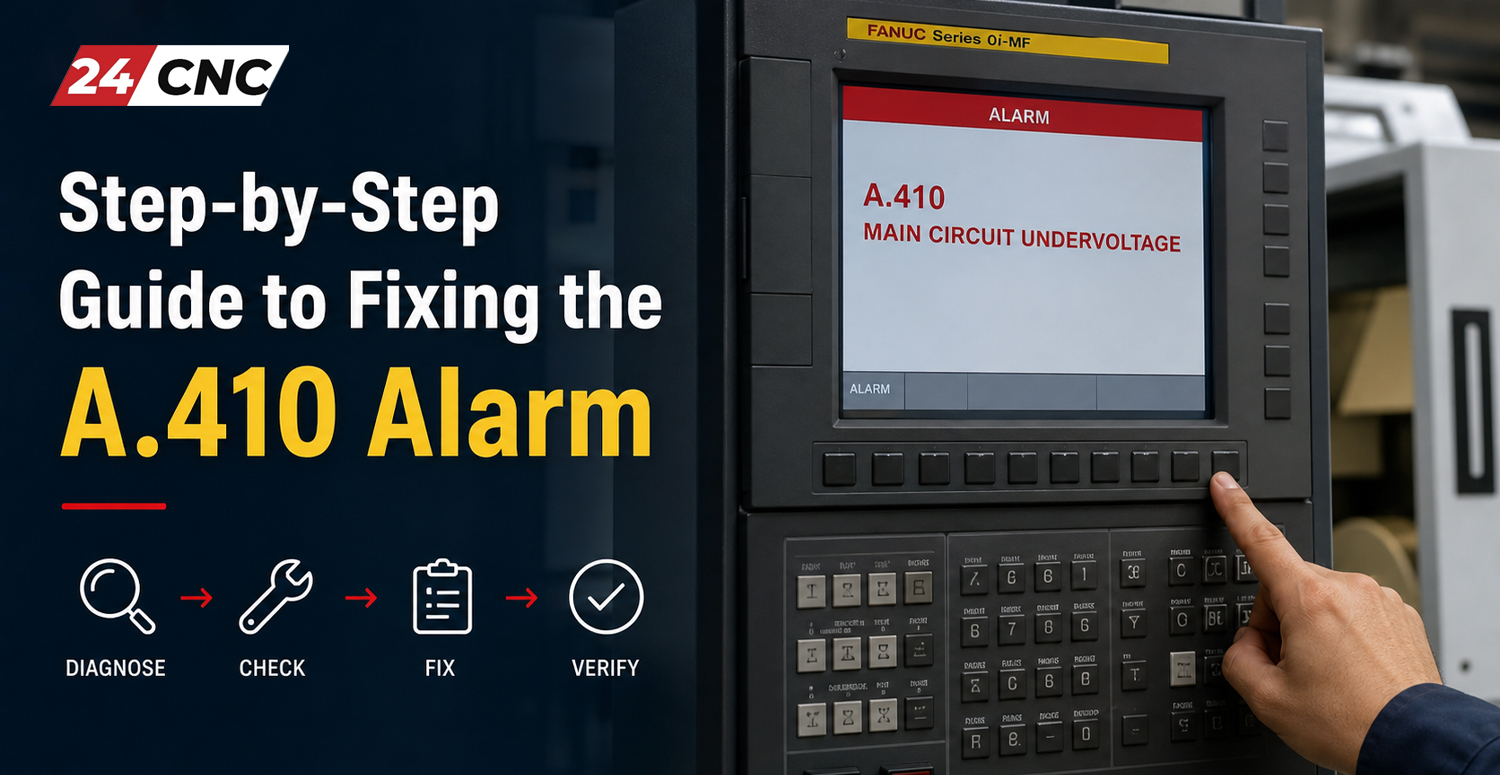
Step-by-Step Guide to Fixing the A.410 Alarm
SAFETY WARNING: CNC servo drives contain lethal voltages. The DC bus can hold charges upwards of 400V to 800V DC for several minutes even after the main machine power is shut off. Always verify that the “CHARGE” indicator LED on the drive is completely off and use a certified multimeter to verify zero voltage before touching any internal terminals. Only qualified personnel should perform these steps.
Step 1: Verify the Incoming Power Supply
Start at the source. Leave the main breaker ON (following proper safety protocols) and use a digital multimeter set to AC Voltage. Measure the incoming power at the main breaker of the CNC machine, and then specifically at the L1, L2, and L3 (or R, S, T) input terminals of the affected servo drive.
- Measure L1 to L2.
- Measure L2 to L3.
- Measure L1 to L3.
All three readings should be balanced and within 10% of your machine’s rated voltage (e.g., 200-230V AC or 380-480V AC). If you detect a massive imbalance or a reading of 0V on one leg, you have a phase loss issue. Check your facility’s breaker panel or inline fuses.
Step 2: Inspect Power Cables and Terminals
If the incoming voltage is correct, turn the machine OFF and perform a Lockout/Tagout (LOTO). Wait for the drive capacitors to discharge. Once safe, take a highly suitable screwdriver and physically check the torque on every single terminal block screw leading from the main breaker, through the contactors, and into the servo drive. A quarter-turn on a loose screw is often all it takes to cure an intermittent A.410 alarm. Look for any signs of heat damage, melted insulation, or blackened wire ends.
Step 3: Evaluate the Magnetic Contactor
With the machine running under a safe, dry-run condition, measure the voltage drop across the main contactor feeding the drive. Measure AC voltage from the input top pole to the corresponding output bottom pole (e.g., L1 IN to T1 OUT). A healthy contactor should show virtually 0V AC across a closed set of contacts. If you read a voltage drop of 5V, 10V, or more, the internal contacts are severely burnt, and the contactor must be replaced.
Step 4: Check the DC Bus Voltage Internally
If all external factors check out perfectly, you must measure the DC bus directly. Locate the DC+ and DC- terminals on the front of the servo drive. Set your multimeter to DC Voltage. Turn the machine on and monitor this voltage. For a 200V AC drive, the DC bus should read approximately 280V DC to 325V DC (Calculated as AC RMS x 1.414). If the DC bus reads significantly lower than this, but the AC input is perfect, the drive’s internal rectifier is faulty.
Step 5: Test Internal Components
If you suspect drive failure, you will need to delve deeper into hardware diagnostics. Advanced technicians can safely power down the system and use a multimeter in “Diode Mode” to test the IGBT modules and the rectifier bridge for short circuits or open circuits. If internal components are blown, the drive will require professional repair or full replacement.
Technical Comparison: A.410 vs. Other Common Voltage Alarms
It is easy to confuse the A.410 Undervoltage alarm with other similar power-related faults. Use the comparison table below to distinguish between common errors and direct your troubleshooting efforts effectively.
| Alarm Code | Description | Primary Trigger | Common Solution |
|---|---|---|---|
| A.410 | Main Circuit Undervoltage | DC Bus drops below safe limit; power loss. | Check AC input power, tighten terminals, inspect contactors. |
| A.400 | Main Circuit Overvoltage | DC Bus spikes too high during motor deceleration. | Check braking resistor, reduce deceleration parameters. |
| A.710 / A.720 | Overload / High Load | Motor pulling too much current for too long. | Check for mechanical binding, check cutting parameters. |
| A.810 | Encoder Battery Fault | Absolute encoder backup battery voltage is low. | Replace the battery while drive power is turned ON. |
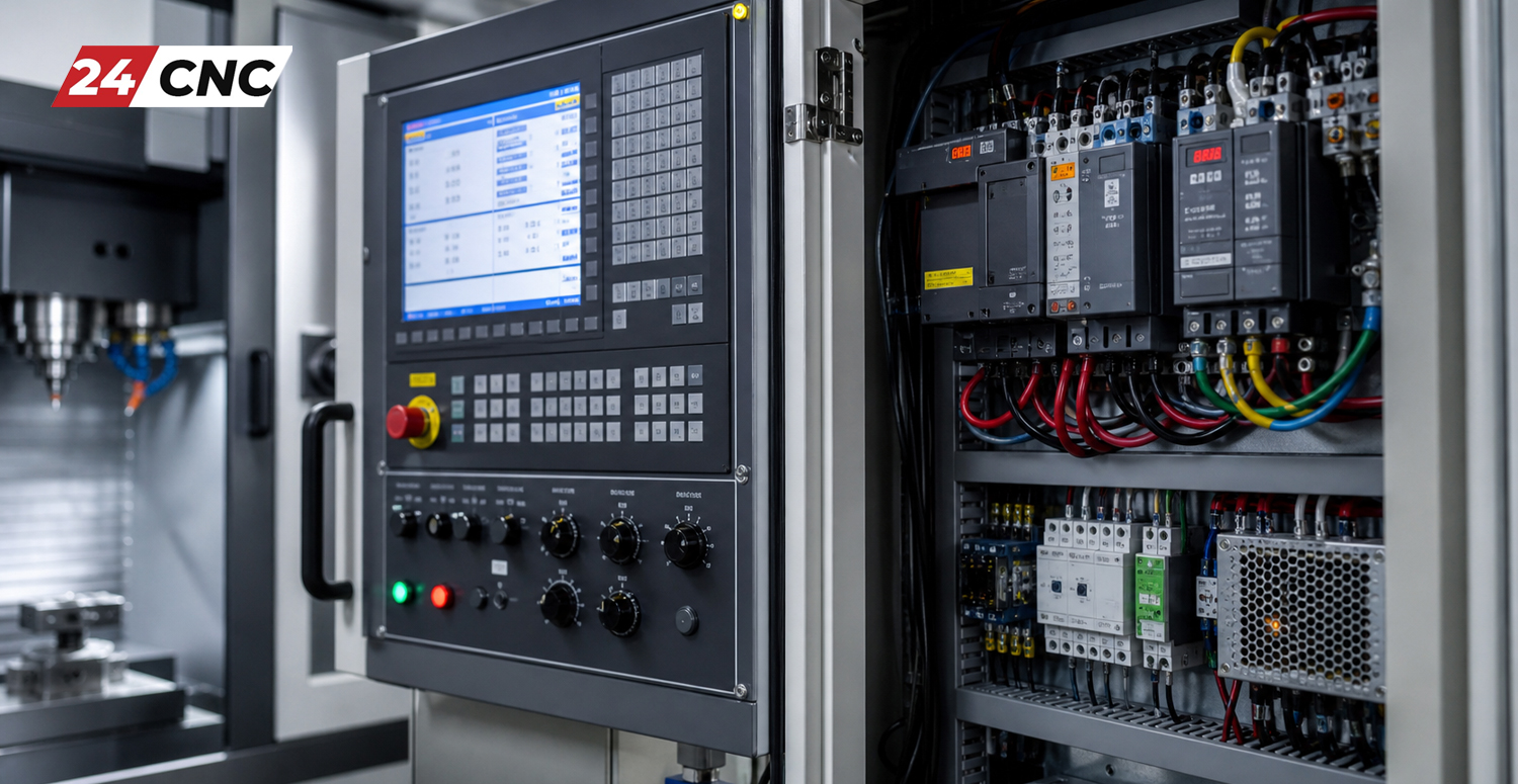
Preventing the A.410 Alarm in Your CNC System
Preventative maintenance is the key to avoiding sudden Undervoltage alarms. Implement these best practices into your shop’s maintenance schedule:
- Implement Regular Electrical Inspections: Every 6 months, schedule downtime to physically re-torque all power terminals in the main cabinet. Thermal expansion and contraction naturally loosen screws over time.
- Monitor Power Quality: If your facility is at the end of a long utility grid line or you operate heavy stamping equipment, consider installing an industrial Voltage Regulator or an Active Voltage Conditioner to stabilize incoming power.
- Thermal Imaging: Use a thermal camera on your electrical cabinet while the machine is running under load. Hotspots on contactors or breakers instantly reveal high-resistance connections before they cause an A.410 fault.
- Keep Cabinets Clean: Dust and coolant mist can create conductive or insulative barriers on electrical contacts. Ensure cabinet fans and filters are clean to maintain optimal airflow and prevent component degradation.
Frequently Asked Questions (FAQ)
Can a faulty servo motor cause the A.410 alarm?
Generally, no. A faulty servo motor usually causes Overcurrent (A.710) or Overload alarms. The A.410 alarm specifically monitors the input power stage and the DC Bus of the amplifier, making it almost entirely related to input power, wiring, or the drive itself.
How do I reset the A.410 alarm?
If the undervoltage condition was temporary (like a momentary power grid dip), you can usually clear the alarm by pressing the “RESET” button on your CNC control panel, or by cycling the main power breaker off, waiting 60 seconds, and turning it back on.
Can I disable or bypass the A.410 alarm parameter?
Absolutely not. The A.410 is a critical hardware-level safety protection. Bypassing it (if even possible through OEM parameters) would force the drive to operate in a power-starved state, resulting in catastrophic failure of the internal IGBTs and capacitors.
What if the A.410 alarm only happens during rapid machine movements?
This strongly indicates a high-resistance point in your power feed (like a bad contactor or loose wire). During rapid acceleration, the motor demands a massive surge of current. The high resistance chokes the current flow, dropping the voltage and triggering the alarm only when under heavy load.
Tackling industrial alarms can be daunting, but with a logical, safety-first approach, the A.410 Main Circuit Undervoltage alarm is easily isolated and repaired. Always start with the simplest solutions—check your incoming power and tighten your screws—before condemning expensive hardware.
Need Replacement Parts to Fix Your A.410 Alarm?
Whether you need a reliable new magnetic contactor, robust power cables, or a complete replacement servo amplifier, 24CNC has the premium industrial components to get your machine running flawlessly.
Browse CNC Amplifiers & Inverters Now
Expert support and global shipping available for all automation professionals.
Leave a comment
Your email address will not be published. Required fields are marked *