

Encountering a sudden stoppage on your CNC machine due to a servo drive fault can be highly stressful, especially when production deadlines are looming. One of the most common and critical faults reported by engineers and machine operators is the Yaskawa A.710 Overcurrent Alarm. If your machine’s interface has suddenly flashed this code, it means the servo amplifier has detected an abnormally high current flowing through the motor line, triggering an emergency protective halt to prevent catastrophic hardware damage.
In the world of industrial automation, understanding how to swiftly diagnose and resolve these electrical anomalies is crucial. Whether you are running a high-speed milling machine or an automated packaging line equipped with Yaskawa products, tackling the A.710 alarm requires a methodical approach. This comprehensive guide will walk you through everything you need to know to safely diagnose, troubleshoot, and fix the Yaskawa A.710 Overcurrent Alarm.
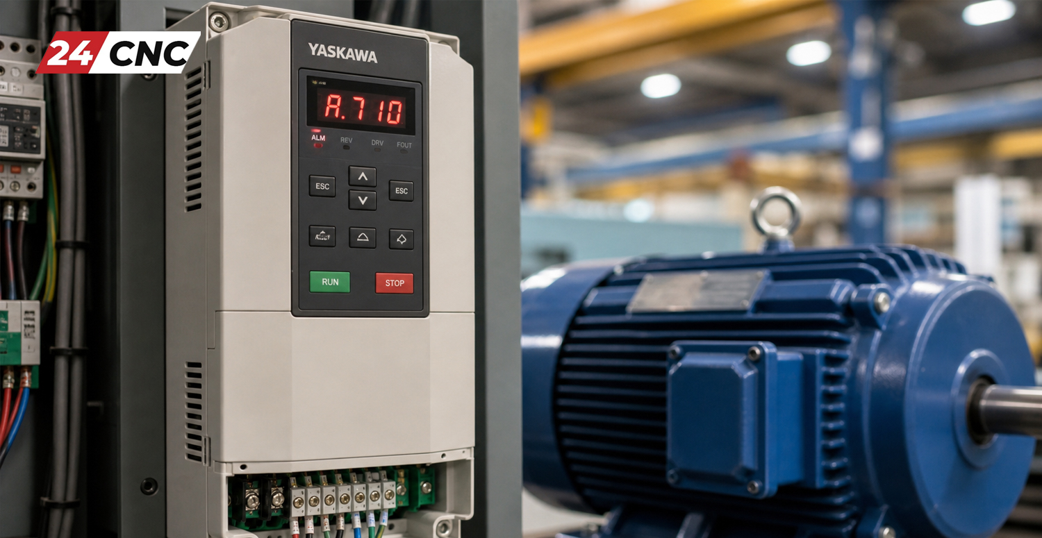
What is the Yaskawa A.710 Overcurrent Alarm?
The A.710 alarm is an instantaneous overcurrent fault. Simply put, the servo drive constantly monitors the electrical current it supplies to the servo motor. If this current exceeds the maximum allowable limit—even for a fraction of a millisecond—the drive’s internal protection circuit trips, cuts the power output, and displays the A.710 code on the digital operator or the CNC control screen.
This protective mechanism is essential. Without it, excessive current would quickly melt wires, destroy the motor windings, or blow the drive’s internal power transistors (IGBTs). Therefore, you must never try to simply reset the alarm repeatedly without investigating the root cause, as doing so can permanently destroy your servo amplifier.
Common Causes of the A.710 Overcurrent Alarm
Before diving into the hands-on troubleshooting, it is important to understand what physically causes this massive surge in electrical current. The reasons typically fall into three primary categories: electrical shorts, mechanical binding, or hardware degradation.
Electrical Short Circuits (Cables and Connectors)
The most frequent culprit behind an A.710 alarm is a short circuit in the UVW power lines running from the drive to the motor. Over time, power cables exposed to moving track chains (cable carriers), cutting fluids, or high-vibration environments can experience insulation breakdown. If phase U, V, or W touches another phase or the machine ground, it creates an immediate low-resistance path, resulting in a massive current spike.
Servo Motor Winding Failure
Inside every servo motor are precisely wound copper coils. If coolant infiltrates the motor housing, or if the motor has overheated in the past, the varnish insulating these copper windings can degrade. This leads to an internal phase-to-phase or phase-to-ground short circuit within the motor stator itself.
Mechanical Overload or Binding
While mechanical issues often trigger overload alarms (like A.720), severe instantaneous binding can also cause an overcurrent fault. If a linear guide seizes, a ball screw jams, or the machine crashes into a hard stop, the motor is suddenly physically locked. The servo drive immediately pumps maximum current trying to overcome this infinite resistance, triggering the A.710 fault before an overload timeout can even register.
Internal Servo Drive Failure (IGBT Module)
If the cables, motor, and mechanics are flawless, the issue lies within the drive itself. The Insulated Gate Bipolar Transistors (IGBT) are the heavy-duty electronic switches that modulate power to the motor. If an IGBT shorts out due to age, heat, or power surges, the drive will instantly read an overcurrent condition the moment power is applied. For more in-depth technical knowledge, reading up on understanding IGBT modules in CNC drives is highly recommended.
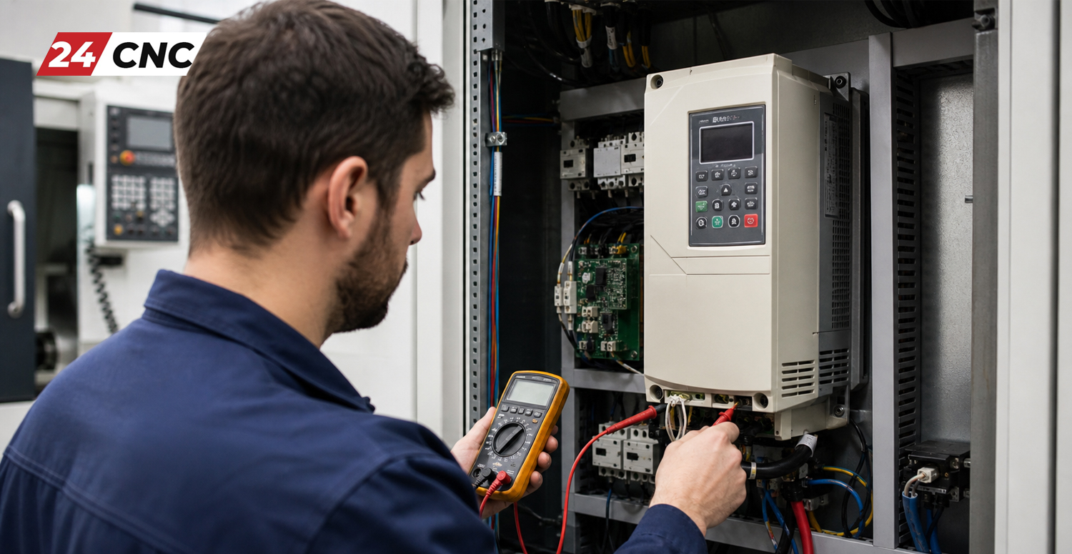
Fix Yaskawa A.710 Overcurrent Alarm: Step-by-Step Troubleshooting Guide
To safely and effectively diagnose and troubleshoot CNC servo amplifier alarms, you must isolate the components one by one. Follow these sequential steps. Safety Warning: Always power down the machine and wait at least 15 minutes for the internal capacitors to discharge before touching any drive terminals.
Step 1: The “Power-On” Isolation Test
First, determine if the alarm happens immediately upon powering the machine, or only when the motor is commanded to move.
- Immediate Alarm: If A.710 appears the second you turn on the control power (before the servo turns on), the servo drive’s internal control board or power section is likely severely damaged.
- Alarm on Servo-On (Enable): If the alarm triggers the moment the machine enables the drives (clicks the contactor), the issue is likely a short in the motor, the power cable, or the drive’s output IGBTs.
- Alarm during motion: If the alarm happens during acceleration or deceleration, suspect mechanical binding, incorrect parameters (acceleration time too aggressive), or a dynamically failing motor cable in a cable track.
Step 2: Disconnect the Motor Power Cable
To isolate the drive from the motor and cables, carefully disconnect the UVW power cables from the bottom of the Yaskawa servo drive. Leave the encoder cable plugged in to prevent an encoder alarm.
Turn the machine on and enable the servos. If the A.710 alarm still appears with no motor attached, you have successfully isolated the problem: The Servo Drive is faulty. The internal IGBTs have failed, and the drive must be repaired or replaced.
If the alarm does not appear when the cables are disconnected, the drive is likely fine. The fault lies downstream in the cable or the motor. Proceed to Step 3.
Step 3: Multimeter and Megger Testing (Motor and Cables)
With the power completely off and locked out, use a standard digital multimeter to measure resistance between the U, V, and W wires at the drive end (while they are still connected to the motor at the other end). The resistance between U-V, V-W, and U-W should be identical and very low (typically a few ohms).
Next, perform an insulation resistance test using a Megohmmeter (Megger). Connect one lead to a solid machine ground and probe the U, V, and W wires. You should read at least 100 Megohms of resistance. If the megger reads 0 or a very low value, you have a short to ground.
To figure out if the short is in the cable or the motor, disconnect the cable directly at the motor plug and repeat the megger test directly on the motor pins. If the motor tests fine, your cable has failed. If the motor tests shorted, the motor windings are damaged and the motor must be rewound or replaced.
Step 4: Check for Mechanical Binding
If electrical tests show no shorts, the issue might be mechanical. Decouple the motor from the ball screw or gearbox. Rotate the mechanical axis by hand. Does it move smoothly? Are the linear rails properly lubricated?
Now, power on the machine with the motor decoupled (spinning in free air). If the motor spins perfectly without triggering the A.710 alarm, your mechanical system is jammed, creating excessive load that spikes the current.
Step 5: Verify Parameters and Dynamic Brake
If you recently replaced the drive or motor, double-check your parameter settings. An improperly tuned system—especially one with an acceleration time (e.g., Pn100 series parameters in Yaskawa Sigma drives) set far too aggressively for a heavy load—will draw massive current. Additionally, check the dynamic brake resistor wiring. A shorted external braking resistor can sometimes cause overcurrent symptoms during rapid deceleration.
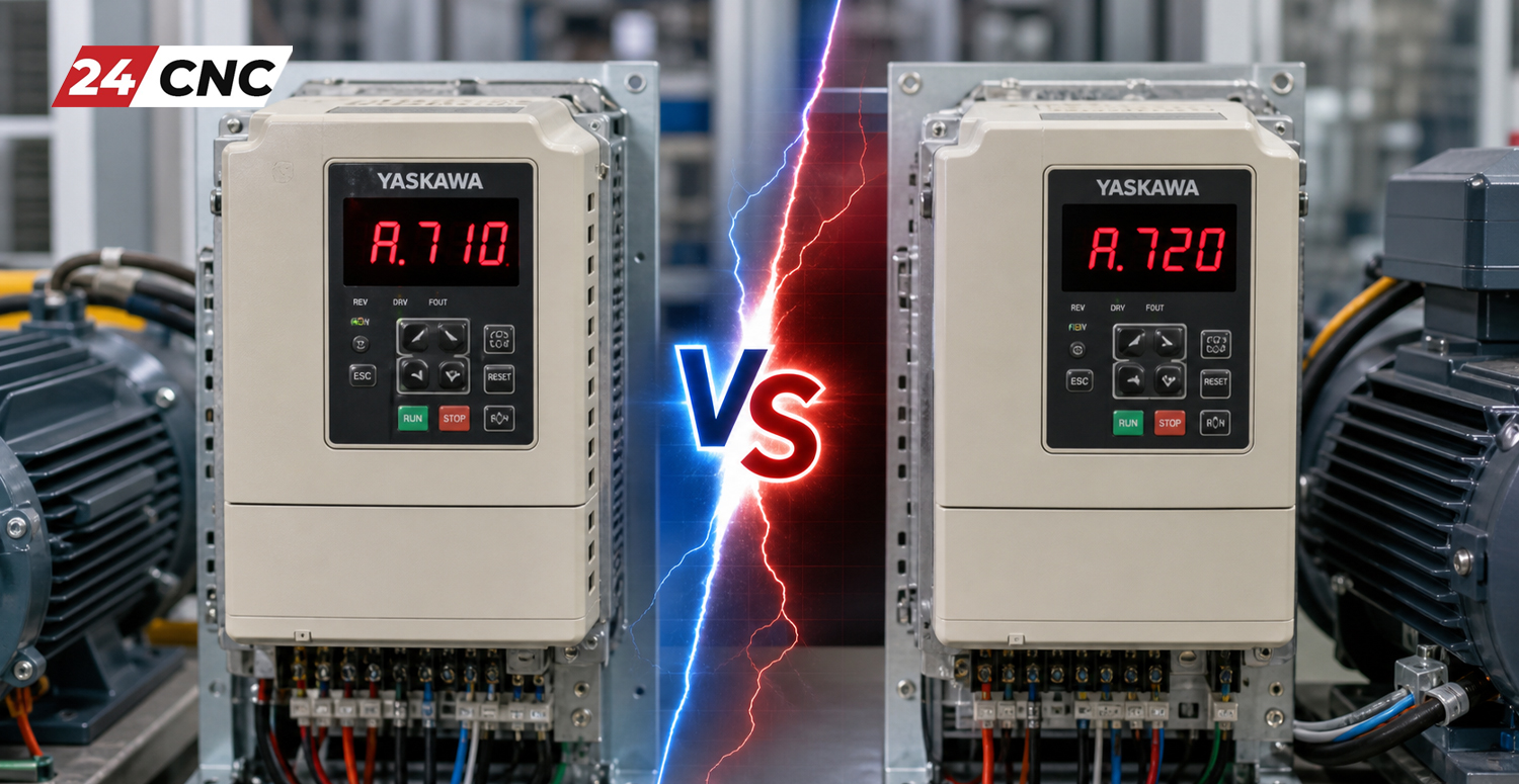
Technical Comparison: Yaskawa A.710 (Overcurrent) vs. A.720 (Overload)
Operators frequently confuse the A.710 Overcurrent alarm with the A.720 Overload alarm. While they sound similar, their electrical definitions and root causes are quite different. Understanding this distinction, similar to understanding the difference between a spindle drive vs servo drive, saves hours of diagnostic time.
Frequently Asked Questions (FAQ)
Q1: Can I just reset the A.710 alarm and keep running my CNC machine?
A: No. Absolutely not. The A.710 is a critical hardware protection fault. If you reset the alarm without fixing a short circuit, the next power surge could violently destroy the internal components of the Yaskawa drive, turning a cheap cable fix into an expensive drive replacement.
Q2: My megger test shows the motor is shorted. Can it be repaired?
A: Yes, servo motors can be rewound by professional electric motor repair shops. However, depending on the age and size of the motor, replacing it with a refurbished or new unit is often more cost-effective and faster for minimizing machine downtime.
Q3: I disconnected the motor cables from the drive, and the alarm still triggers. What does this mean?
A: If the motor is completely disconnected and the drive still throws an A.710 alarm upon enabling, the internal IGBT (Insulated Gate Bipolar Transistor) module or the current sensing circuit board inside the Yaskawa drive has failed. The drive must be sent in for professional repair.
Q4: Does the A.710 alarm mean my encoder is bad?
A: Very rarely. Encoder failures typically throw different alarms (such as A.810 or A.820). The A.710 is strictly related to high voltage power output to the motor phases, not the low voltage feedback signals from the encoder.
Conclusion: Getting Your Machine Back Online
Fixing the Yaskawa A.710 Overcurrent Alarm requires patience, proper safety protocols, and a logical process of elimination. By isolating the drive from the motor and cables, performing accurate multimeter and megger tests, and verifying mechanical integrity, you can pinpoint the exact source of the short circuit or hardware failure. Remember, never ignore protective alarms—they are designed to save your expensive industrial equipment from further catastrophic damage.
Need High-Quality CNC Replacement Parts?
Don’t let a faulty drive, damaged cable, or burned-out motor stall your production. At 24CNC, we stock a massive inventory of premium replacement parts, tested components, and automation accessories to get your machines running flawlessly.
Leave a comment
Your email address will not be published. Required fields are marked *