
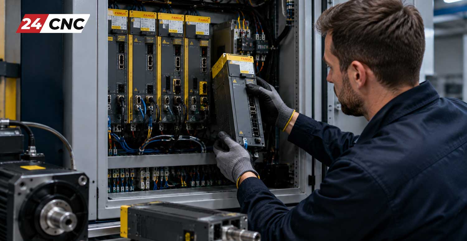
In the world of high-precision CNC manufacturing, unexpected axis drive failures translate directly to lost revenue, missed delivery dates, and idle labor. When a CNC machine throws an unrecoverable axis fault, the root cause is frequently a failed servo drive module. Knowing the correct, safe, and efficient protocol for replacing a faulty Fanuc servo amplifier is an indispensable skill for CNC maintenance technicians, automation engineers, and machine shop owners.
This comprehensive technical guide outlines the complete end-to-end process: from diagnosing a blown drive unit and safety preparations to step-by-step mechanical swapping, parameter configuration, and post-installation validation. Whether dealing with a classic Fanuc Alpha series or modern modular Alpha-i systems, this guide provides the practical engineering insight required to bring your machine tool back to life safely.
1. Confirming the Diagnosis: Is the Servo Amplifier Really Defective?
Before ordering a costly replacement unit, you must verify that the fault lies strictly within the servo amplifier module and not within peripheral components such as the motor windings, feedback sensors, or power cabling. In our detailed resource on how to diagnose and troubleshoot CNC servo amplifier alarms, we explore specific alarm interpretations. However, prior to physical replacement, perform these critical checks:
A. Check the Amplifier Status Display
Fanuc servo amplifiers feature a 7-segment LED display on the front fascia. If the drive is ready, it shows 00 or --. Specific hardware alarms—such as Alarm 8, Alarm 9, Alarm b, or Alarm L—point directly to high-current conditions, DC link undervoltage, internal IPM failures, or communication bridge breakdowns.
B. Static Diode Test on the Output IGBTs
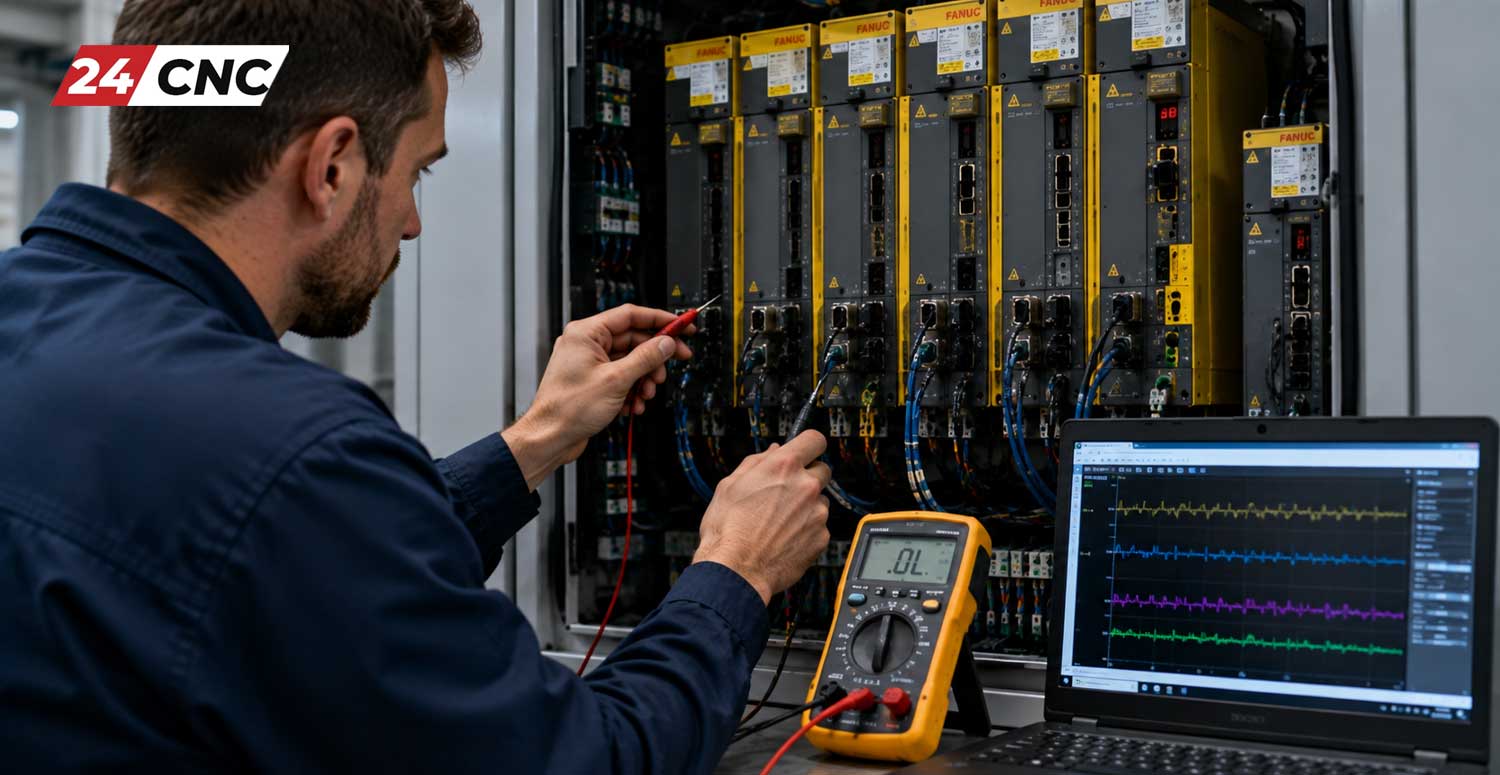
A rapid way to confirm catastrophic drive failure is checking the internal IGBT modules. With the power disconnected and discharged:
- Place a digital multimeter in Diode Check mode.
- Measure between the DC link negative ($-$) terminal and the $U, V, W$ motor terminals. Expect a forward drop of $0.3\text{V}$ to $0.5\text{V}$ and open-circuit ($OL$) in reverse.
- Measure between the DC link positive ($+$) terminal and the $U, V, W$ terminals.
- A reading of $0.00\text{V}$ indicates a shorted power bridge, confirming the need to swap the module.
C. Isolate the Axis Motor and Cables
Disconnect the motor power lead at the amplifier terminal block. Use a 500V or 1000V Megohmmeter to verify that the Fanuc servo motor windings and connected power cables maintain greater than $10\,\text{M}\Omega$ of insulation resistance to earth ground. If the insulation tests cleanly, the drive is definitively faulty.
2. Pre-Replacement Preparation and Safety Procedures
Industrial CNC cabinets house lethal voltages. High-capacity DC bus capacitors can hold charges exceeding $300\text{V} \text{ DC}$ to $600\text{V} \text{ DC}$ long after the main breaker is tripped. Adhere strictly to the following safety protocols:
- Implement Lockout/Tagout (LOTO): Disconnect incoming 3-phase factory mains to the CNC machine. Lock the disconnect switch and tag it to prevent accidental re-energization.
- Wait for Discharge: Wait a minimum of 10 to 15 minutes to allow the discharge circuit within the Fanuc power supply module (PSM) to drain stored capacitance.
- Verify Zero Energy State: Using a calibrated multimeter set to DC voltage, measure across the DC Link terminals (labeled $L+$ and $L-$). Verify that the voltage has dropped below $10\text{V} \text{ DC}$ before touching terminal screws or bus bars.
- Backup Critical CNC Parameters: Prior to shut-down, back up all system parameters, SRAM contents, and pitch error compensation data via an SRAM card or Ethernet directly from the Fanuc controller.
3. Step-by-Step Hardware Replacement Procedure
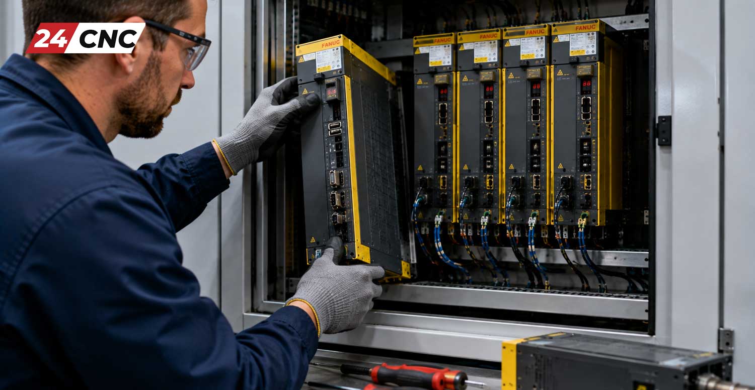
When handling specialized Fanuc drive amplifiers, following a disciplined removal and insertion process prevents damage to delicate control electronics and optical interfaces.
Step 1: Label and Disconnect Signal Cabling
Take high-resolution reference photographs of the wiring layout. Carefully unclip the FSSB (Fanuc Serial Servo Bus) optical fiber cables from ports COP10A and COP10B. Optical fiber cables have a maximum bend radius (typically $\ge 25\text{mm}$); sharp bends can fracture the internal glass core. Unplug the feedback encoder leads (JF1, JF2, or JF3 connectors).
Step 2: Remove Bus Bars and Power Terminations
Unfasten the upper DC bus bars linking the SVM (Servo Module) to the adjacent PSM or SPM. Remove the 24V control power connector (CXA2A/CXA2B) and the motor output phases ($U, V, W$). Inspect the drive-side connectors for signs of heat discoloration, pitting, or carbon tracking.
Step 3: Unfasten and Extract the Chassis
Loosen the mounting screws (typically M4 or M5 fasteners) securing the drive frame to the cabinet backplane. Modern Fanuc Alpha-i drives utilize keyed mounting slots: loosen the bottom screws, remove the top screws, and lift the drive upward to unseat the rear external heatsink.
Step 4: Check Internal Cooling and Peripheral Components
Before installing the new unit, ensure that external heatsink channels are free from dried coolant sludge and swarf. Verify that the dedicated drive controller cooling fan on the replacement unit spins freely and has no bearing friction, as thermal accumulation is the leading secondary cause of premature transistor failure.
Step 5: Mount and Reconnect the Replacement Drive
Seat the replacement amplifier onto the mounting studs and torque all chassis screws evenly. Reattach the DC bus bars, ensuring screws are firmly torqued according to manufacturer specifications (typically $2.0 \text{ N}\cdot\text{m}$ to $2.5 \text{ N}\cdot\text{m}$). Loose DC link bolts create localized resistance, resulting in arcing and thermal destruction of the terminal block. Re-engage all signal and optical cables precisely as tagged.
4. Configuration, Absolute Encoder Batteries, and Axis Commissioning
Physical replacement is only part of the process. Bringing the axis back to operational tolerance requires careful setup and encoder zero-point alignment.
- Handling Absolute Pulse Coder (APC) Batteries: If your system utilizes absolute feedback via a Fanuc rotary encoder, the battery backup keeps track of the machine’s reference coordinates when the main power is off. If the battery connector is attached directly to the amplifier unit (CX5X/CX5Y port), transfer the battery module immediately to prevent losing machine zero reference.
- FSSB Optical Bus Re-Initialization: If installing a multi-axis amplifier (e.g., dual-axis $\alpha i\text{SV } 40/40$ or triple-axis unit) in a modified arrangement, navigate to the FSSB initialization screen on the CNC display to verify that the controller recognizes axis slot assignments correctly.
- Setting Reference Return (Home Position): If the encoder lost reference during replacement, an
APC 300 Alarm (Need ZRN)will appear. Jog the axis near the home stroke and execute an axis-specific Zero Reference Return sequence, or adjust Fanuc Parameter1815#4 (APZ)in accordance with machine builder specifications.
Technical Comparison: Fanuc Servo Amplifier Architectures
Understanding the differences between Fanuc drive series ensures you select the correct direct-fit replacement and matching interface protocols for your CNC configuration:
5. Post-Installation Testing and Validation Protocol
Do not return the machine directly to high-speed production. Follow a controlled bring-up procedure to ensure safe operation:
- Control Power On Only: Power on the CNC control while keeping the Emergency Stop engaged. Verify that the 7-segment display on the new drive initializes properly and communicates over the optical link without FSSB disconnect alarms.
- Clear Emergency Stop in Low Override: Release the E-stop. Observe the drive status (it should switch to
00indicating normal ready status). - Slow Manual Jog Verification: Select Manual Jog mode at $1\%$ or $5\%$ rapid feed override. Move the axis in both positive ($+$) and negative ($-$) directions, verifying correct motion direction and absence of high-frequency vibration or motor humming.
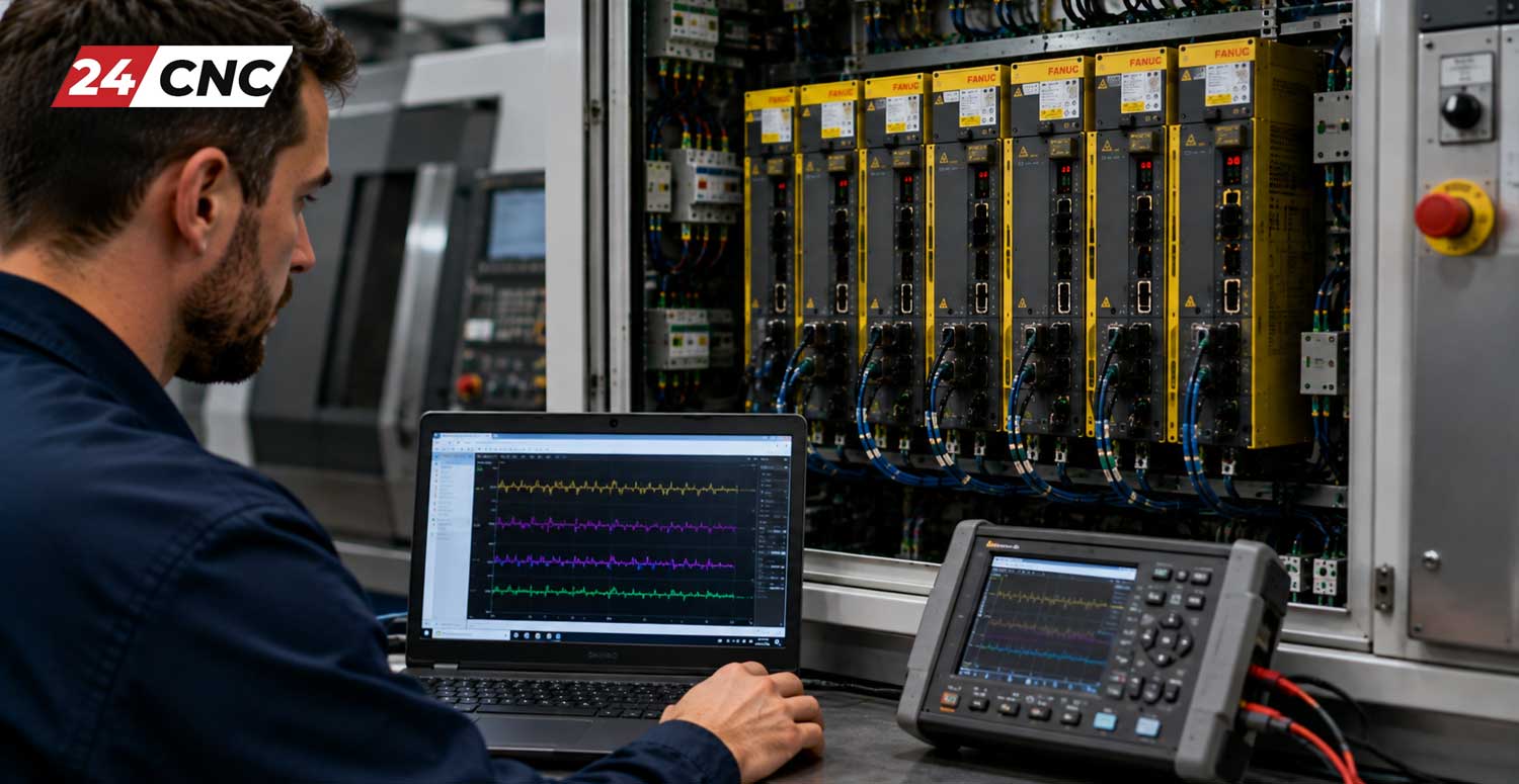
- Check Axis Current Load: Navigate to the CNC Servo Monitor Screen. Inspect the steady-state current load during standstill. Standard stationary load across linear axes should typically remain below $15\%$ to $25\%$. Elevated static load suggests mechanical binding or improper tuning parameters.
Sourcing Certified Replacement Drives
When facing downtime, installing unreliable or untested components poses a serious operational risk. Poorly rebuilt amplifiers with counterfeit power transistors can fail catastrophically and damage adjacent power modules or servo motors. Understanding where to buy high-quality CNC parts online ensures you procure fully tested, genuine components complete with reliable warranty coverage and technical support.
Frequently Asked Questions (FAQ)
Can I swap a single-axis Fanuc servo amplifier with a different revision?
Generally, you must match the exact part number (e.g., A06B-6114-H104). While certain later hardware revisions are backwards-compatible, mismatching the internal control board or output current rating can trigger configuration errors or overload the motor.
Why does my Fanuc drive show alarm “8”, “9”, or “A” immediately after replacement?
These codes represent high-current (IPM overcurrent) alarms. If an alarm triggers immediately upon releasing the E-stop, it typically points to a grounded motor phase, shorted power cable, or a phase sequence mismatch ($U, V, W$ wired incorrectly).
Do I need to re-enter CNC servo parameters when replacing a drive?
In standard Fanuc architectures, servo parameters are stored in the CNC main controller motherboard (SRAM), not inside the modular servo amplifier. As long as the replacement part number matches, the control will automatically push parameters to the drive via FSSB upon boot.
How can I prevent my new Fanuc servo amplifier from failing prematurely?
Maintain clean cabinet cooling filters, inspect external cooling fans annually, keep electrical enclosures sealed against oil mist, and regularly check cable carrier tracks for power line insulation fatigue.
Need a Replacement Fanuc Servo Drive Immediately?
Avoid costly machine downtime. 24CNC supplies fully tested, authentic Fanuc servo amplifiers, power supplies, motors, and cooling assemblies with fast dispatch and expert technical guidance.
100% Quality Tested • Rapid Global Logistics • Engineering Support
Leave a comment
Your email address will not be published. Required fields are marked *