
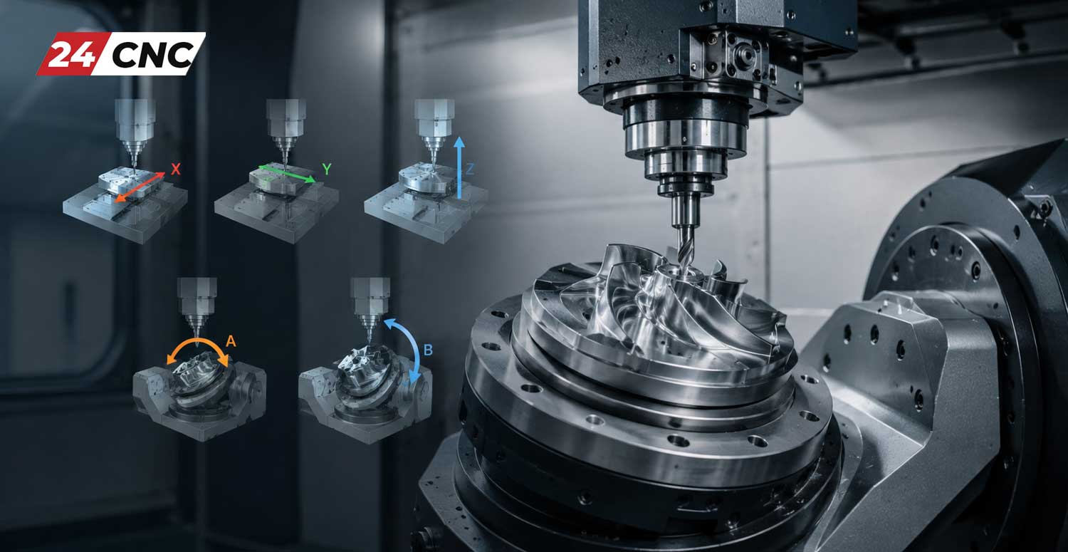
The evolution of Computer Numerical Control (CNC) machining has fundamentally transformed modern subtractive manufacturing. From the earliest days of punch-tape Numerical Control (NC) to today’s highly sophisticated, software-driven machining centers, the core of this technological marvel lies in the concept of CNC machine axes. Whether you are an engineer designing complex aerospace geometries, a procurement manager sourcing capital equipment for a large-scale industrial facility, or a workshop owner looking to upgrade your capabilities, understanding the transition from standard 3-axis mills to highly complex 5-axis machining centers is an absolute necessity.
The number of axes dictates a machine’s capabilities, the geometrical complexity of parts it can successfully produce, the type of workholding required, and the overall efficiency of the production cycle. Moving from three axes to five axes is not merely adding more motors; it represents an exponential leap in mathematical complexity, machine kinematics, processing power, and operational strategy. In the era of Industry 4.0, optimizing your machining setup directly correlates with your facility’s profitability and ability to bid on high-tolerance contracts.
In this comprehensive, deep-dive guide, we will explore the foundational principles of CNC axes, break down the specific functionalities, mechanics, and programming nuances of 3-axis, 4-axis, and 5-axis machines. Furthermore, we will examine the essential components of a CNC machine that make precise multi-axis movement possible on the micrometer scale, ensuring your shop floor remains at the cutting edge of manufacturing technology.
The Foundation of Subtractive Manufacturing: 3-Axis CNC Machining Explained
The standard 3-axis CNC vertical milling machine (VMC) and horizontal machining center (HMC) remain the undisputed workhorses of the global manufacturing industry. They operate on the fundamental principles of the Cartesian coordinate system, utilizing three orthogonal linear axes to manipulate the rapidly spinning cutting tool relative to the stationary workpiece.
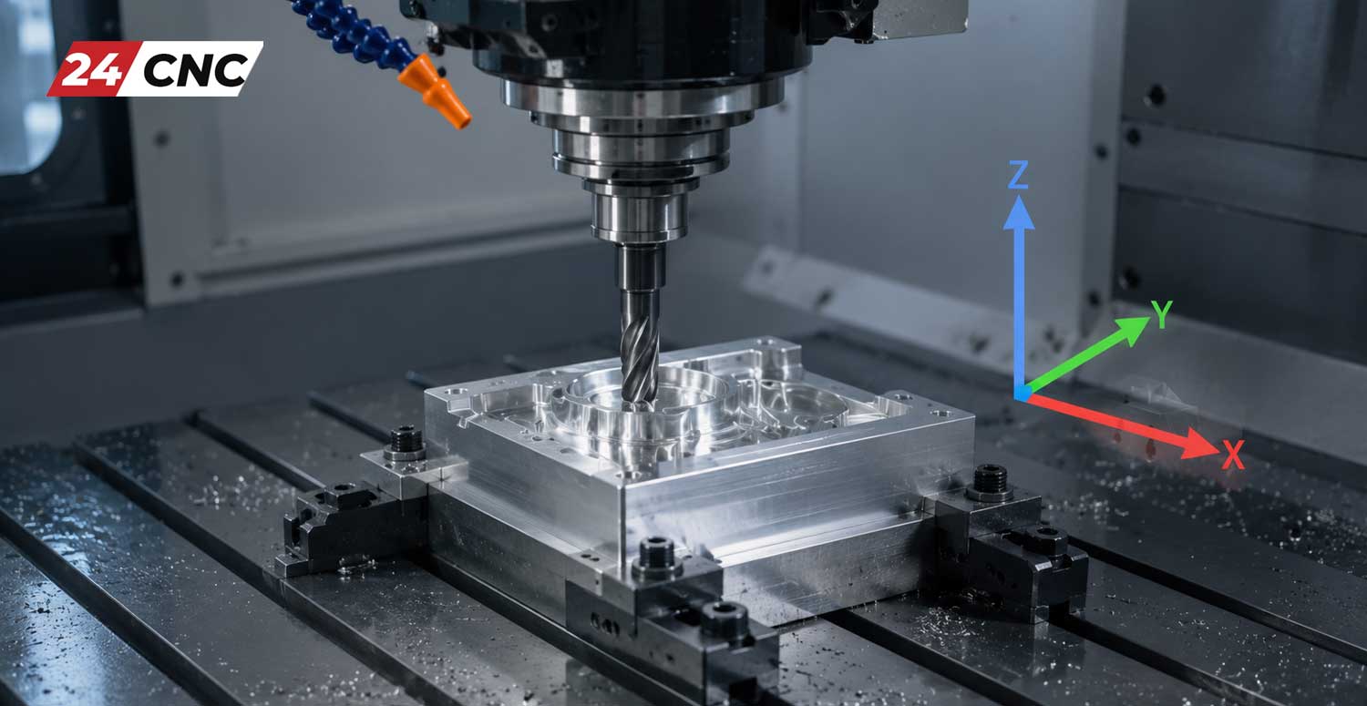
The Cartesian Coordinate System ($X, Y, Z$)
In a strict 3-axis system, movement occurs exclusively along three linear directions. Mathematically, the position of the cutting tool’s tip can be defined at any given moment by a vector $V = (x, y, z)$ within a three-dimensional geometric space:
- $X$-Axis: Represents the longitudinal movement. On a typical VMC, this is the movement of the machine table left and right, parallel to the machine’s longest dimension.
- $Y$-Axis: Represents the transverse movement. This is the movement of the saddle (or table) front and back, moving toward or away from the machine operator.
- $Z$-Axis: Represents the vertical movement. This dictates the up and down motion of the spindle head, driving the tool into or out of the workpiece.
During 3-axis machining, the workpiece is clamped rigidly to the machine table—using mechanical vises, hydraulic clamps, or custom-machined fixtures—and remains entirely stationary throughout the cycle. The CNC controller interpolates the movement of the cutting tool along the $X$, $Y$, and $Z$ axes simultaneously to carve out the programmed shape. From a programming perspective using standard EIA/ISO G-code, linear positioning is commanded via rapid traverses ($G00$) and linear interpolation feeds ($G01$), while circular interpolation relies on $G02$ and $G03$ calculated across a defined plane (e.g., $G17$ for the $XY$ plane, $G18$ for $XZ$, or $G19$ for $YZ$).
Mechanics, Rigidity, and Tooling in 3-Axis Mills
The physical movement in these machines is achieved through heavy-duty cast-iron box ways (for extreme rigidity and dampening) or linear guide rails (for high-speed rapid movements), driven by precision ground ball screws. As the servo motor turns the ball screw, the rotational motion is converted into highly precise linear motion. 3-axis machines utilize a wide array of cutting tools, including flat end mills, ball nose end mills, face mills, thread mills, and carbide drill bits.
Because the spindle orientation remains fixed (always pointing straight down along the $Z$-axis in a VMC), the type of geometry that can be cut is limited by the tool’s profile and the fact that the tool can only approach the part from above. If a deep cavity needs to be machined, a long cutting tool must be used. This leads to increased tool deflection and harmonic vibration (chatter), forcing the programmer to reduce feed rates and depth of cut, ultimately slowing down production.
Primary Applications and Inherent Limitations
3-axis machines are incredibly efficient, highly rigid, and highly cost-effective for planar milling, drilling hole patterns, rigid tapping, and 2.5D profiling. They are the go-to solution for manufacturing engine blocks, simple electronic enclosures, flat mounting plates, and brackets.
However, their primary limitation is the absolute inability to reach undercuts or machine complex geometries on the lateral sides of a part without manual repositioning. If a part requires machined features on all six sides of a cube, the operator must machine one side, stop the machine, unclamp the part, physically rotate it, re-indicate the zero datum point, clamp it again, and load a new program. This manual intervention drastically increases setup time, creates bottlenecks in production scheduling, and introduces a high potential for alignment errors (stack-up tolerances) with every subsequent setup.
Bridging the Gap: The Introduction of 4-Axis CNC Machining
To overcome the severe limitations of stationary workpieces and multiple manual setups, the 4-axis CNC machine introduces a single rotary axis. This addition represents a monumental paradigm shift in manufacturing efficiency, dramatically reducing setup times, increasing volumetric accuracy, and unlocking the ability to machine cylindrical or wrapped geometric features.
The Mechanics of the A-Axis
A standard 4-axis CNC machine retains the baseline $X, Y$, and $Z$ linear axes and seamlessly integrates a rotational axis. By standard mathematical convention, rotation around the $X$-axis is designated as the $A$-axis. If the rotation were around the $Y$-axis, it would be termed the $B$-axis. On a vertical milling machine, adding a 4th-axis rotary table (often referred to as an indexer) aligned with the $X$-axis is the most prevalent configuration.
By rotating the workpiece mathematically by an angle $\theta$ on the $A$-axis, the cutting tool gains direct access to the sides of the raw material. This means that features on four sides of a rectangular prismatic part, or features wrapped continuously around a cylinder, can be machined in a single, uninterrupted clamping operation.
Indexing (3+1) vs. Simultaneous 4-Axis Machining
It is critical for manufacturing engineers and machinists to distinguish between the two highly distinct operational modes of 4-axis machining:
- Indexing 4-Axis (Positional 3+1): Often referred to as “3+1 machining,” the $A$-axis rotates the part to a specific calculated angle $\theta$, applies a powerful mechanical, pneumatic, or hydraulic brake to lock the rotation into a completely rigid position, and then the machine performs standard 3-axis cutting ($X, Y, Z$) on that newly exposed face. Once the toolpath is finished, the tool retracts to a safe clearance plane, the brake releases, the $A$-axis indexes to the next programmed angle, and the process repeats. This is excellent for drilling cross-holes in shafts or machining multiple sides of a valve body.
- Continuous (Simultaneous) 4-Axis: In this highly dynamic mode, the machine is capable of actively cutting material while the $A$-axis is rotating in perfect, real-time synchronization with the $X, Y$, and $Z$ axes. The CNC controller must constantly calculate the feed rate of the rotating part so that the surface speed of the cutting tool remains constant relative to the changing diameter of the part. This usually requires programming with Inverse Time Feed ($G93$). Simultaneous 4-axis is strictly utilized for creating complex continuous profiles like performance camshafts, helical gears, extrusion augers, and simple turbine blades.
Tombstone Machining and High-Volume Production Efficiency
In high-volume production environments, 4-axis Horizontal Machining Centers (HMCs) are the standard. They utilize “tombstones”—large, extremely rigid, multi-sided cast-iron fixtures mounted directly to the machine’s B-axis rotary table. Operators can clamp dozens of identical parts to the various faces of the tombstone. The machine works on one face, indexes the rotary axis, and begins machining the next set of parts without missing a beat. Coupled with automatic pallet changers (APC), this maximizes spindle up-time and forms the cornerstone of highly profitable, “lights-out” automated manufacturing.
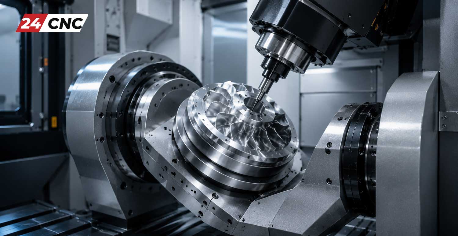
The Pinnacle of Precision: 5-Axis CNC Machining Centers
5-axis CNC machining represents the absolute pinnacle of subtractive manufacturing technology and modern kinematic engineering. These monumental machines can manufacture highly intricate parts with organic, sweeping, and undercut geometries in a single setup. They are indispensable in industries where micrometer precision is non-negotiable and geometries are immensely complex, such as the aerospace sector (jet engine blisks, impellers, titanium structural bulkheads), automotive racing (cylinder heads with complex 5-axis porting), and the medical sector (custom titanium bone implants, artificial hip joints, and dental prosthetics).
Defining the B and C Axes
A true 5-axis machine utilizes the standard linear $X, Y, Z$ axes and introduces two of the three possible rotary axes ($A, B$, or $C$). Typically, this configuration involves:
- $B$-Axis: Rotation around the $Y$-axis.
- $C$-Axis: Rotation around the $Z$-axis.
By articulating the cutting tool or pivoting the machine table along these two additional rotary axes simultaneously, the machine can approach the workpiece from virtually any spherical direction. The mathematical calculations required to maintain the tool tip position across five constantly moving planes are immense, relying heavily on complex vector mathematics, Euler angles, and high-speed processor look-ahead capabilities.
Machine Configurations: Trunnion vs. Swivel Head
5-axis machines are engineered and built in two primary hardware configurations, each suited for specific types of manufacturing:
- Trunnion Table Configuration: The workpiece is mounted directly on a rotary table that provides the $C$-axis (spinning 360 degrees like a record player). This table is mounted inside a heavy cast-iron cradle (the trunnion) that tilts back and forth to provide the $A$ or $B$ axis (typically $+30$ to $-120$ degrees). The spindle remains in a fixed vertical orientation, moving only in $X, Y$, and $Z$. This setup provides massive rigidity, excellent chip evacuation, and is excellent for heavy material removal on medium-sized parts.
- Swivel Head (Articulating Head) Configuration: The workpiece remains completely stationary on a large flat table (or spins on a simple flush-mounted $C$-axis), while the heavy machine spindle itself articulates, swivels, and tilts to provide the necessary rotary axes. This configuration is absolutely ideal for machining incredibly heavy, bulky, or oversized parts—like aerospace wing spars, automotive clay models, or massive injection molds—where tilting a multi-ton part on a trunnion would be physically impossible and dynamically unstable.
Tool Center Point Control (TCPC) and Kinematics
The most crucial software feature of modern 5-axis machining is TCPC (Tool Center Point Control), sometimes called RTCP (Rotation Tool Center Point). Without TCPC, rotating an axis moves the physical part away from the spindle, requiring the CAM software to rigidly hard-code the exact $X, Y, Z$ positions based on the exact pivot lengths of that specific machine. If a tool length changes by even $0.1mm$, the entire program must be reposted.
With TCPC activated (often via $G43.4$ in Fanuc controls or `TRAORI` in Siemens controls), the CNC controller takes over the heavy kinematic math. The controller automatically drives the $X, Y$, and $Z$ linear axes to dynamically compensate for the rotary movement. This ensures the physical tip of the cutting tool remains locked onto the programmed coordinate on the part, regardless of how the table or head tilts. This allows for truly portable G-code that can be moved between different 5-axis machines.
Positional (3+2) vs. Full Simultaneous 5-Axis
Similar to 4-axis systems, 5-axis machines operate in two primary modes:
- 3+2 Machining (Positional 5-Axis): The machine uses the two rotary axes to position the part at a fixed, compound spatial angle in 3D space. Once locked rigidly in position, a standard 3-axis milling operation is executed. This is perfectly suited for machining deep cavities, facing off complex angles, or drilling angled holes on multiple sides of a prism in a single “done-in-one” setup.
- Full Simultaneous 5-Axis: All five axes ($X, Y, Z, B, C$) move continuously and synchronously. The cutting tool smoothly glides over complex contoured surfaces, constantly altering its tilt vector to maintain an optimal cutting angle relative to the surface normal. Advanced techniques like Swarf Milling (cutting with the side or flank of the end mill) and Point Milling become possible. This allows for the use of much shorter, more rigid cutting tools, which completely eliminates vibration (chatter), drastically increases tool life, and produces a mirror-like surface finish that requires zero manual hand-polishing.
Technical Comparison Matrix: 3-Axis vs. 4-Axis vs. 5-Axis
| Technical Feature | 3-Axis CNC | 4-Axis CNC | 5-Axis CNC |
|---|---|---|---|
| Axes of Movement | $X, Y, Z$ (Strictly Linear) | $X, Y, Z$ + $A$ (Linear + 1 Rotary) | $X, Y, Z$ + $A/B/C$ (Linear + 2 Rotary) |
| Geometrical Complexity | Low to Medium (2.5D, basic planar 3D) | Medium to High (Cylindrical wraps, cams) | Extremely High (Organic 3D surfaces, blisks) |
| Manual Setup Interventions | Multiple required for multi-sided parts | Significantly reduced (4 sides in one setup) | “Done in One” (Complete single-setup machining) |
| Tool Length Requirements | Longer tools needed for deep pockets (prone to chatter) | Moderate tool length | Short, highly rigid tools (head tilts to avoid body collisions) |
| Capital Cost & Programming | Lowest capital cost, simple manual conversational G-code possible | Moderate investment, basic CAM software required | Highest investment, advanced CAM and machine kinematics simulation mandatory |
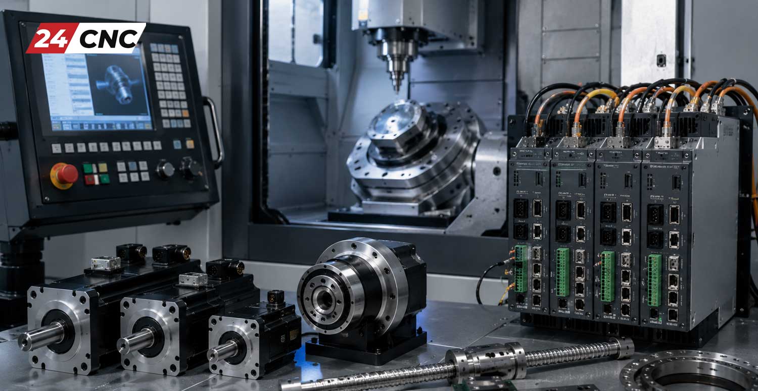
Crucial CNC Hardware Components for Multi-Axis Control
The physical movement of three to five heavy cast-iron or polymer-composite axes with sub-micrometer precision requires highly sophisticated electronic and mechanical hardware. A machine tool is only as accurate and reliable as its weakest component. Upgrading, maintaining, or retrofitting these advanced machining centers means thoroughly understanding the high-performance parts that drive them.
Advanced Control Systems: The “brain” of the machine is the CNC control system. It interprets the CAM software’s massive G-code files—which can routinely exceed millions of lines of code for a complex 5-axis aerospace mold—and coordinates the exact timing, acceleration (jerk), and deceleration of every axis. High-end simultaneous multi-axis machining relies heavily on robust industrial controllers with massive processing power. For example, a Fanuc controller (like the 31i-B5 series) or a Siemens controller (like the Sinumerik ONE) features advanced multi-core processors capable of incredibly fast block-processing speeds (“look-ahead” capabilities up to thousands of blocks) and real-time kinematic calculations to ensure smooth, gouge-free toolpaths without data starvation.
Servo Motors & Amplifier Drives: To move the heavy axes smoothly and accurately, modern CNC machines utilize highly responsive closed-loop industrial servo motors paired with intelligent digital servo amplifier drives. Unlike older open-loop stepper motors that can easily lose steps if pushed too hard during roughing, AC brushless servo motors provide continuous, real-time positional and velocity feedback directly to the controller. This closed-loop feedback system ensures the axis is exactly where the mathematical model says it should be, even under violent, heavy roughing loads in tough materials like Inconel or Titanium.
Precision Rotary Encoders and Glass Scales: Precision is entirely meaningless without exact, independent verification. Rotary encoders (and linear glass scales for the $X, Y, Z$ axes) are attached to the rear of the servo motors or directly bolted to the ball screws and rotary platters to track the exact rotational or linear physical position of the machine axis. In high-end 5-axis machines, absolute optical or magnetic encoders with resolutions measuring in the nanometers are completely mandatory. Absolute encoders ensure the machine knows its exact physical position the millisecond it is powered on, eliminating the need for a tedious homing/zeroing sequence and maintaining incredibly tight thermal tolerances across complex, multi-day 3D toolpaths.
Frequently Asked Questions (FAQ)
Is a 5-axis machine always a better choice than a 3-axis machine?
Not necessarily. While a 5-axis machine is vastly more capable and flexible, it is also significantly more expensive to purchase, maintain, tool up, and insure. Furthermore, programming a 5-axis machine requires highly expensive CAM software licenses (like Mastercam, HyperMill, or Siemens NX) and highly skilled, specialized programmers. For manufacturing simple, flat, or prismatic parts in high volumes, a rigid, ultra-fast 3-axis machine is often far more cost-effective, easier to operate, and yields a faster return on investment (ROI).
What exactly is “kinematics” in the context of multi-axis CNC?
Kinematics refers to the complex mathematical relationship and exact physical geometry between the moving parts of a specific machine tool. Because pivot points, rotation centers, and spindle lengths vary by machine build, the CNC controller must use a kinematic model to perform spatial calculations in real-time. This coordinates the linear ($X,Y,Z$) and rotary ($A,B,C$) axes so the cutting tool tip remains exactly on the programmed path despite the part tilting drastically away from the spindle’s zero point.
What is “Gimbal Lock” or a “Singularity” in 5-axis machining?
A singularity (often compared to Gimbal Lock in aerospace) occurs in 5-axis machining when two rotary axes align perfectly with each other, causing the machine to mathematically lose a degree of freedom. When the CAM toolpath crosses exactly over this singularity point, the machine must physically rapidly whip its rotary axes 180 degrees to maintain the tool vector. This sudden, violent motion can leave massive gouge marks on the part, break the tool, or exceed the machine’s axis limits. Advanced CAM programmers must carefully tilt the tool vector slightly away from zero to avoid passing directly through singularity zones.
Can I upgrade my existing 3-axis VMC to a 4-axis or 5-axis system?
In many cases, yes. You can often add a third-party aftermarket rotary table (4th axis) or a bolt-on trunnion table (4th and 5th axis) directly to the T-slots on the bed of a 3-axis machine. However, the machine’s control system and internal wiring cabinet must have the computational capacity, available amplifier drives, pre-wired fourth/fifth axis cables, and unlocked software parameter options (often requiring a paid unlock code from the manufacturer) to accept and simultaneously control the additional axes.
What role does CAM software and Machine Simulation play in 5-axis machining?
Computer-Aided Manufacturing (CAM) software is absolutely vital and non-negotiable for 5-axis work. While a human can manually write conversational G-code for simple 3-axis parts, calculating the complex spatial vectors and dynamically changing tool vectors for simultaneous 5-axis movement is mathematically impossible for a human brain. Advanced CAM software generates these complex toolpaths. Equally important is Machine Simulation software (like Vericut), which creates a digital twin of the machine to manage collision avoidance—ensuring the massive spinning spindle doesn’t crash catastrophically into the tilting trunnion table or fixtures before the program ever runs on the real machine.
Keep Your Multi-Axis CNC Running at Peak Performance
Whether you are running a standard 3-axis high-speed production mill or pushing the absolute limits of modern manufacturing with a state-of-the-art simultaneous 5-axis machining center, machine downtime is your biggest enemy. Ensure your axes move with absolute micrometer precision, eliminate costly servo following errors, and maintain your competitive manufacturing edge by using genuine, high-quality replacement electronics and mechanical components.
Leave a comment
Your email address will not be published. Required fields are marked *