
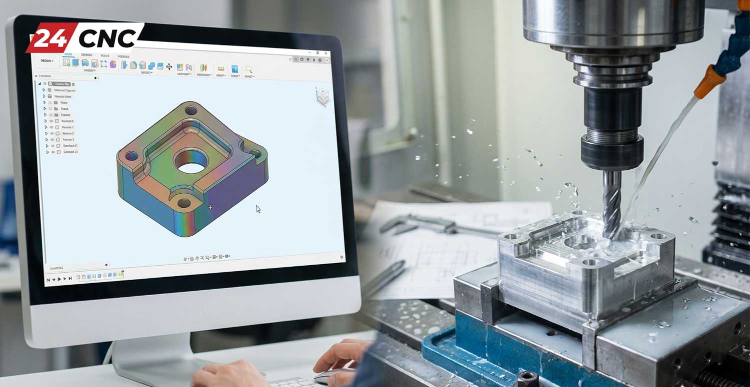
Designing parts for Computer Numerical Control (CNC) machining can feel daunting for beginners and even seasoned engineers shifting from additive manufacturing. The transition from a digital 3D CAD model to a physical, precision-milled metal or plastic component involves understanding the complex physical constraints of cutting tools, material behaviors, machine kinematics, and control systems. Whether you are building rapid prototypes for a hardware startup, engineering aerospace components, or optimizing a part for high-volume production, mastering Design for Manufacturability (DFM) is non-negotiable.
Properly designing for CNC machining not only guarantees the structural integrity and functionality of your part but also drastically reduces the final manufacturing costs and lead times. When designs are optimized for the machine, cycle times drop, tool wear is minimized, and the load on critical machine components—like spindle motors and servo drives—is kept within optimal parameters.
This comprehensive guide will walk you through the core principles of designing parts specifically for CNC mills and lathes. We will cover the critical aspects of part geometry, tolerances, material selection, surface finishes, and how modern CNC control systems interpret your designs, ensuring you can confidently send your next project to the machine shop.
1. Understanding the Subtractive Manufacturing Process
Before diving into specific design rules, it is crucial to understand that CNC machining is a strictly subtractive manufacturing process. Unlike 3D printing (additive manufacturing), which builds parts layer by layer, CNC machining starts with a solid block of raw material (the blank or billet). It then uses high-speed rotating cutting tools to aggressively and precisely remove material until the final shape remains.
The cutting tools—such as end mills, drills, and face mills—are cylindrical and rotate on a primary axis. This fundamental geometric reality dictates almost every CNC design rule. Because the tools are round, they cannot easily produce perfectly sharp internal corners or complex internal cavities that are entirely enclosed. Your design must account for tool access and clearance. If the cutting tool cannot reach a feature without colliding with another part of the workpiece, the machine cannot cut it. While advanced 5-axis machines, driven by sophisticated Fanuc or Siemens controllers, offer extraordinary flexibility by rotating the part in real-time, the core subtractive limitations of tool geometry still apply.
2. The Challenge of Internal Corners and Radii
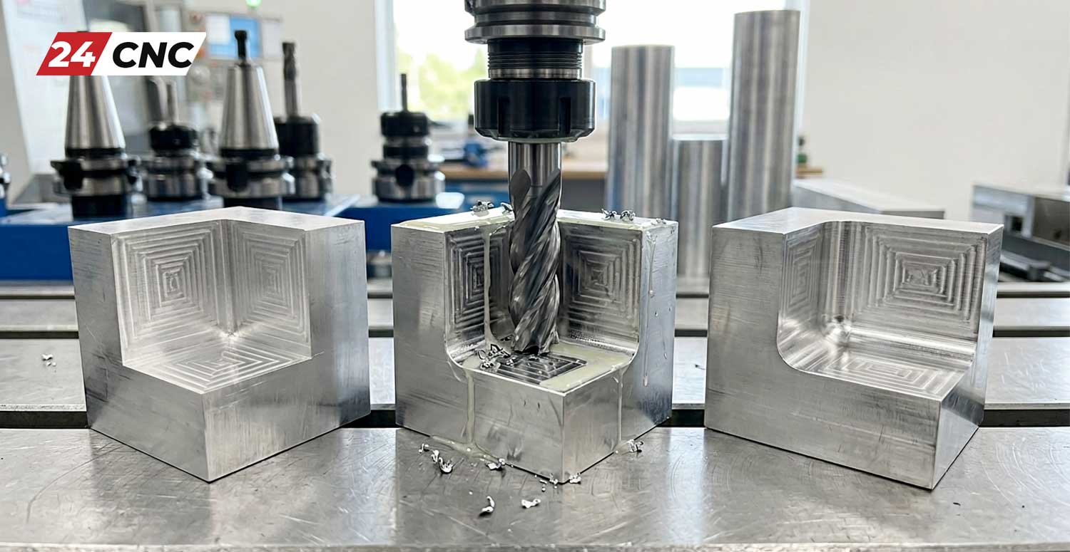
The most common and costly mistake beginners make is designing sharp, $90^{\circ}$ internal corners. Because milling tools are cylindrical, they naturally leave a radius when cutting an internal corner. Attempting to force a sharp internal corner requires the machinist to use progressively smaller tools, which drastically increases machining time. If a perfectly sharp corner is absolutely necessary for part mating, it typically requires highly expensive secondary operations like Electrical Discharge Machining (EDM) or broaching.
The DFM Rule for Corners: Always add a fillet (radius) to internal vertical edges. As a standard rule of thumb, make the corner radius ($R$) slightly larger than one-third of the cavity depth ($D$). Mathematically, ensure $R > 0.33 \times D$. More ideally, aim for $R \ge 130\%$ of the milling tool’s radius. A larger radius allows the machine shop to use a larger, more rigid end mill. Larger tools remove material faster, vibrate less, and reduce machining costs. If a rectangular mating part needs to fit squarely into a pocket, do not design a sharp corner; instead, utilize a “dog-bone” or “T-bone” undercut at the corners to provide relief for the mating part.
3. Managing Cavities, Pockets, and Wall Thickness
When designing pockets or cavities, the depth-to-width ratio is a major cost driver. Long cutting tools are highly susceptible to deflection (bending) and vibration (chatter) during the cutting process. Chatter ruins the surface finish, reduces dimensional accuracy, and can easily snap the cutting tool or damage the machine’s tool holder.
Design Rule for Pockets: Limit the depth of your pockets to $4 \times$ the width of the pocket. For example, if a pocket is $10 \text{ mm}$ wide, its maximum depth should ideally not exceed $40 \text{ mm}$. If you must go deeper (up to $6 \times$ or $10 \times$), expect the machine shop to charge a premium for specialized long-reach tooling, vibration-damping tool holders, and significantly slower feed rates.
Design Rule for Wall Thickness: Very thin walls are incredibly difficult to machine. The lateral pressure exerted by the cutting tool causes thin material to flex away from the cutter, leading to severe inaccuracies, warping, or tearing of the material. For structural metal parts (like aluminum or steel), maintain a minimum wall thickness of $0.8 \text{ mm}$. For softer plastics, maintain a minimum of $1.5 \text{ mm}$. Thicker walls increase the structural stability of the part during the intense stress of the machining process. If thin walls are required, they must be machined in multiple, very light passes, which increases machine time and cost.
4. CNC Milling vs. CNC Turning
It is vital to understand which type of CNC machine will produce your part, as the design rules differ slightly:
- CNC Milling: The workpiece remains stationary (or rotates on specific axes), and the rotating cutting tool moves around it. Milling is ideal for prismatic, flat, or complex 3D shapes.
- CNC Turning (Lathes): The raw material (a cylindrical rod) rotates at high speeds in a chuck, while a stationary cutting tool moves linearly to shave off material. Turning is perfect for cylindrical parts like shafts, bushings, and spacers.
If your part is primarily cylindrical, design it to be turned on a lathe, as turning is generally much faster and cheaper than interpolating a cylinder on a mill. Modern CNC lathes often feature “live tooling,” meaning they have small milling cutters on the turret, allowing for off-axis holes, flats, and slots to be machined on a cylindrical part in a single setup.
5. Tolerances and GD&T: Do Not Over-Specify
Tolerances define the acceptable margin of error for a given dimension. While CNC machines equipped with high-resolution rotary encoders and powerful servo motors are incredibly precise, asking for tighter tolerances than strictly necessary is a guaranteed way to inflate your budget unnecessarily.
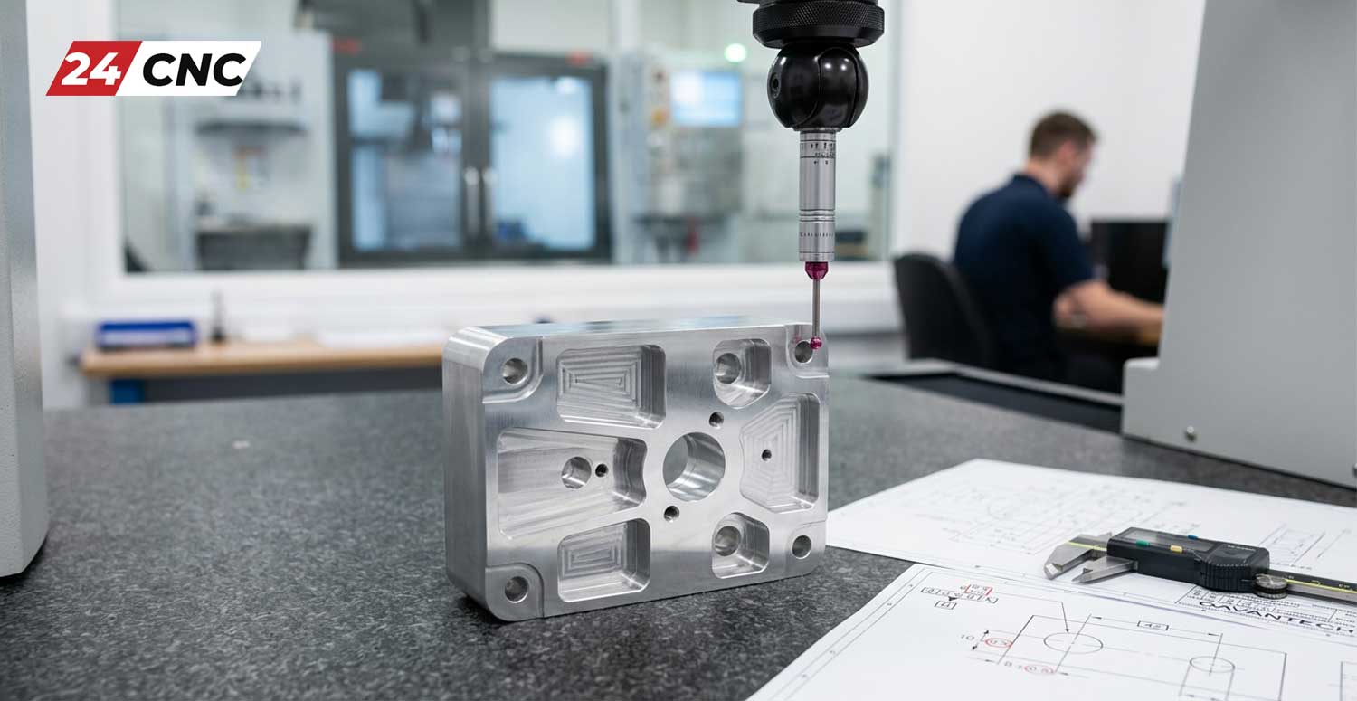
A standard CNC machining process can comfortably and economically hold a tolerance of $\pm 0.125 \text{ mm}$ (approximately $\pm 0.005 \text{ inches}$) according to ISO 2768 standard guidelines. If you specify tighter tolerances (e.g., $\pm 0.025 \text{ mm}$ or $\pm 0.01 \text{ mm}$), the machinist must use brand-new tools, drastically slow down the cutting speeds, account for thermal expansion of the machine and the part, and perform rigorous manual inspections using micrometers or a Coordinate Measuring Machine (CMM).
Best Practice: Only apply tight tolerances to critical features, such as bearing press-fits, alignment dowel holes, or critical sealing surfaces. Leave the rest of the non-critical geometry to standard block tolerances. Furthermore, consider utilizing Geometric Dimensioning and Tolerancing (GD&T) to control features like flatness, parallelism, and concentricity, which often provides more manufacturing flexibility than strict dimensional tolerances.
6. Standardizing Holes and Threads
Holes and internal threads are ubiquitous in CNC parts, but they can be problematic if designed poorly.
- Hole Diameters: Custom hole sizes require custom drill bits or time-consuming circular interpolation with an end mill. To keep costs down, design your holes to match standard fractional, wire-gauge, or metric drill bit sizes (e.g., $3.0 \text{ mm}$, $3.3 \text{ mm}$, $4.0 \text{ mm}$).
- Hole Depth: The depth of a hole should ideally not exceed $4 \times$ its diameter (a $4:1$ ratio). Deep hole drilling requires specialized “peck drilling” cycles to clear chips and prevent drill breakage.
- Threads: When designing threaded holes, remember that thread length does not need to extend to the very bottom of a deep blind hole. The maximum holding strength of a threaded fastener is achieved in the first few threads. A thread depth of $1.5 \times$ to $3 \times$ the nominal hole diameter is mathematically sufficient for maximum tensile strength. Always specify standard thread pitches (like $M4 \times 0.7$, $M6 \times 1.0$, or $1/4-20 \text{ UNC}$) rather than custom profiles.
7. Material Selection Guide
The raw material you specify dramatically impacts the machining process, tooling wear, and final cost. Materials are rated by their “machinability”—a measure of how easily they can be cut.
- Aluminum (6061-T6 & 7075-T6): The most common CNC materials. They have excellent machinability, dissipate heat well, and cause minimal tool wear. 6061 is highly economical for general parts, while 7075 offers aerospace-grade strength.
- Stainless Steel (304 & 316): Much harder and tougher than aluminum. They tend to work-harden during machining, requiring rigid setups, heavy coolant flow, and slower cutting speeds. 316 offers superior corrosion resistance compared to 304 but is slightly harder to machine.
- Carbon Steels (1018, 4140): Good balance of strength and machinability. 4140 can be heat-treated for exceptional hardness, making it ideal for gears and high-stress mechanical components.
- Plastics (Delrin/POM, PEEK, Polycarbonate): Plastics cut very quickly but are prone to warping and melting if heat builds up. Delrin (Acetal) is widely considered the best plastic for CNC machining due to its high dimensional stability and low friction. PEEK is a high-performance, high-temperature plastic but is exceedingly expensive as a raw material.
8. Specifying Surface Finishes
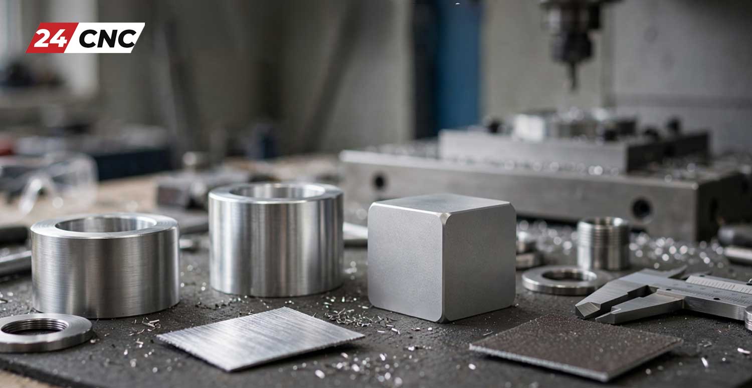
The standard “as-machined” surface finish for CNC parts will show visible tool marks. Surface roughness is typically measured as Roughness Average ($Ra$) in micrometers ($\mu\text{m}$). A standard, cost-effective CNC finish is usually $Ra = 3.2 \mu\text{m}$ ($125 \mu\text{in}$).
If you require a smoother finish for aesthetic reasons or O-ring seals, you can specify $Ra = 1.6 \mu\text{m}$ or $Ra = 0.8 \mu\text{m}$. However, achieving these smooth finishes requires the machine to make very slow, fine finishing passes, which increases the cycle time. For aesthetics, consider post-processing options like bead blasting (which provides a uniform matte finish) or anodizing (for aluminum parts to add color and corrosion resistance) rather than forcing the CNC machine to achieve a mirror finish.
CNC Design Rules Checklist: A Quick Reference
Use this technical comparison table as a pre-flight checklist to ensure your CAD designs are fully optimized for the CNC manufacturing process before requesting a quote.
| Design Feature | Recommended DFM Practice | Cost Impact if Ignored |
|---|---|---|
| Internal Corners | Add fillets with a radius $R > 0.33 \times$ pocket depth. Avoid $90^{\circ}$ angles. | High (Requires tiny, fragile tools or expensive EDM). |
| Pocket Depth | Maximum depth should be $\le 4 \times$ the pocket width. | Medium (Risk of tool deflection, chatter, and poor finish). |
| Wall Thickness | Min. $0.8 \text{ mm}$ for structural metals, $1.5 \text{ mm}$ for plastics. | High (Warping, part rejection, requires slow multi-pass milling). |
| Tolerances | Use standard ISO 2768 ($\pm 0.125 \text{ mm}$). Only tighten critical interfaces. | Very High (Exponentially increases setup, cutting, and QA time). |
| Holes and Threads | Use standard drill sizes. Thread depth maximum $3 \times$ diameter. | Low to Medium (Custom tooling or difficult chip evacuation). |
| Surface Finish | Accept standard $Ra = 3.2 \mu\text{m}$. Use bead blast for uniform aesthetics. | Medium (Smooth finishes require lengthy, low step-over finishing passes). |
Frequently Asked Questions (FAQ)
1. Can a CNC machine create undercuts?
Yes, but they require specialized tools like “lollipop” cutters, T-slot cutters, or dovetail cutters. Because standard end mills cut straight down on the Z-axis, an undercut is a feature that cannot be seen directly from above. Designing undercuts significantly increases setup complexity and machining time. Avoid them if the design permits.
2. How do I know if my part requires a 3-axis or 5-axis CNC?
If your part can be machined from a single direction (or flipped $180^{\circ}$ manually) without needing to be repositioned for angled holes or features, a standard 3-axis vertical machining center (VMC) is sufficient. If the part requires features on multiple faces at complex, off-axis angles (like an impeller or a complex manifold), a 5-axis machine is necessary. While 5-axis reduces manual setup changes, the machines carry a much higher hourly operating rate.
3. Does adding text, logos, or part numbers to my part increase the cost?
Yes, significantly. Milling text requires switching to tiny engraving tools and adds considerable time to the G-code machining cycle as the tool traces the geometry. If branding or serialization is required, consider secondary post-processes like laser engraving, dot peen marking, or silk-screening, which are almost always faster and cheaper than CNC engraving.
4. What is the best format to export my CAD files for CNC machining?
The industry standard for sharing 3D models for CNC machining is the STEP (.step or .stp) file format. It is a robust, solid-body format that retains accurate geometrical data regardless of the CAD/CAM software used by the machine shop. Avoid sending mesh files like STL (.stl) unless you are doing 3D printing, as STLs do not contain the precise mathematical curves and surfaces required for accurate CNC toolpath generation.
5. Should I design my parts with chamfers or fillets on the outside edges?
Sharp exterior edges are dangerous to handle and prone to chipping. It is standard practice to “break” all sharp edges. A simple $0.5 \text{ mm} \times 45^{\circ}$ chamfer is generally faster and cheaper for a CNC machine to produce using a chamfer mill compared to an exterior fillet, which requires a specific corner-rounding end mill or time-consuming 3D profiling.
Conclusion
Designing for CNC machining is fundamentally an exercise in practical, reality-based engineering. By deeply understanding the physical limitations of the subtractive process—such as tool reach, internal corner radii dynamics, material machinability, and the implications of tight tolerances—you can design robust, beautiful parts that are highly cost-effective to produce. Applying these standard Design for Manufacturability (DFM) principles from the very beginning of your CAD process ensures smooth communication with your machine shop, minimizes costly design revisions, accelerates lead times, and ultimately results in an end product that perfectly matches your engineering vision.
Maintain Peak Machining Precision
Executing perfect designs requires machinery that operates flawlessly, shift after shift. Whether you are upgrading your shop’s capabilities or performing critical maintenance, using reliable control boards, high-accuracy encoders, and durable drives is essential. Ensuring your CNC equipment is maintained with top-tier, genuine components is the secret to consistent, high-yield manufacturing quality.
Leave a comment
Your email address will not be published. Required fields are marked *